Upon completion of this lesson students should be able to:
Explain what ground failure is.
Describe methods in ground control.
Compare and contrast the different types of supports.
Reading & Lecture
Purposes & Policies in Ground Control
Provide protection from ground failure
Company policy for ground control at the mine
Causes of Ground Failure
Loose rock
Large boulders
Back arches
Type of rock
Sagging of the back
Seeping water
Rock bursts
Adjacent blasting
Adjacent caving
Redistribution of the load on the back
Rock fractures or faulting
Rock vibrations from adjacent work
Failure of back support devices
Gouging of back by mining equipment
Rock fall
Most hazards are rocks falling & causing other rocks to fall
[Play animation]
Toe Failure
Unconsolidated materials occur when weight forces bottom to bulge and fail
[Play animation]
Slope Failure
Cracks allow slabs to detach and slide
(Play animation)
Block Flow
Cracks allow rock to separate in towers and fall over and outwards
[Play animation]
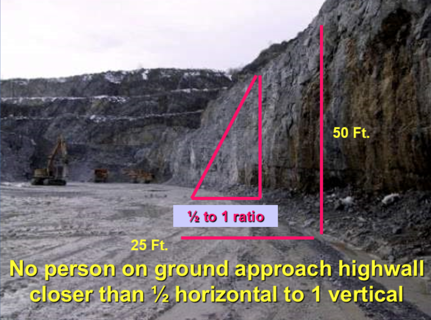
[Wall approach limit diagram]
2007 Utah Crandall Canyon Mine Disaster:
A major ground failure due to coal bumps
Started room & pillar mining in 1939 and changed to longwall mining in 1995
Produced 3.5 million tons per year at the time of disaster
The mine panel is 1500 feet underground.
The accident took place on August 6, 2007.
Coal bumps (rock/coal bursts) caused collapsing of the mine panel and six miners were trapped.
Ten days later, three rescue workers were killed by a subsequent coal bump.
Methods in Ground Control
Testing back and side for loose rock
The method of removing loose rock from the back or side is called barring down or scaling down. A metal pry bar called a scaling bar is used.
Loose rock gives off a hollow or dull sound when hit with a hammer or scaling bar, compared to a solid ring of a sound back. Loose rock is also detected by visual inspection of protruding rock, cracks, and deteriorating pillars. Skill in identifying loose rock requires practice.
Safe work habits while barring down.
Stand under a safe area, preferably one already tested for loose rocks.
Do not stand directly beneath the loose rock which you are barring down. Pry away from you rather than toward you.
Assure yourself a safe route of retreat. Do not put your back up against the side because you may become trapped.
Often more rock will come down than you might expect.
Time line for support of the back
Temporary support provides immediate support in an active working area for a relatively short period of time.
Permanent support provides support over a longer period of time. It is used in areas of high foot and/or equipment traffic or in long-life haulageways, shops, power distribution centers, storage areas, lunch rooms, and pump rooms.
Temporary Supports
Wooden posts with cap blocks and wedges.
Screw-type jacks that extend as the handle is turned, along with cap blocks.
Hydraulic jacks that extend as the handle is pumped.
Spilling involves inserting rods into the sides and back at several points along a drift.
Forepoling involves insertion of poles into the face of a development drift or stope. The poles are either all wood or half wood and half metal. The wood section would eventually be mined out, leaving the metal section in the rock for support.
Stuns are thick wood posts used to support protruding rock. Wedges are used to secure the post against the rock.
Permanent Supports
Rock bolts are metal rods at least four feet long which are installed in drilled holes in the back or side. The point anchor rock bolt consists of a long threaded bolt and an expansion shell that expands when the bolt is tightened to anchor the bolt in the rock. A bearing plate fits between the bolt head and the back to distribute the weight of the rocks. Bolts are tightened to a predetermined torque which is periodically checked. Rock bolts provide several methods of support:
The beam method draws together several layers of rock, making a strong beam of supporting rock. Fully grouted resin bolts are used to make the beams.
The suspension method passes rock bolts through weak layers of rock and tightens into a higher main rock layer with a point anchor expansion type bolt.
Wire matting is held up by several rock bolts and is used to catch smaller pieces of rock that might fall between bolts.
Trusses are metal plates or strips held up by several rock bolts. Trusses are bent to conform to the shape of the back.
Resin type bolts employ resin and hardening agent packed in sausage-like tubes. These tubes are placed in the drill hole. When the bolts are inserted and spun, the resin tubes break and the hardener is mixed with the resin. The bolt is then held tightly against the side or back until the resin sets enough to prevent the bolt from slipping out, usually about 30 seconds.
The split set is similar to the rock bolt except that the bar is hollow with a one inch gap along its length. The bar is squeezed and inserted into the drill hole. As the bar attempts to spring back open its own force keeps it wedged in the hole. Split sets may be used with wire matting or trusses
Concrete is used for back, side, and floor support in drifts, draw points, and ore passes. Forms are set and concrete laid to provide as much support as necessary.
Shotcrete (or gunite) is similar to concrete. It keeps moisture from the rock and helps prevent sloughing off, but does not have the same strength as concrete.
Timbering is also known as the conventional method of ground control. Timbers or posts are placed between the back and floor, usually against the sides. Crossbars span the posts along the roof, forming a three-piece set. This supports a wide area, such as a haulageway. Wedges are used to tighten the fit between the post and back or floor.
With a three-piece set of timber, lagging may be used to join posts placed on the same side to prevent loose rock from falling into the haulageway.
With a three-piece set of timber, cribbing involves placing smaller three-piece sets above one another to fill unsupported space. Timber then contacts the entire width of the back, and can support a very heavy load.
Yieldable arches use four steel braces, two against the sides and two curved to fit the arch of the back. The back-side braces are joined by a friction clamp. Increased back pressure is compensated for by slippage through these clamps. In addition, the distance between the floor and connections between the two back braces indicates rock sag.
Responsibilities for Back and Ground Control
Responsibility of management and supervision
Routine inspections of the back to identify hazards.
Routine testing of torque on rock bolts.
Responsibility of miners.
Identifying hazardous ground conditions and reporting these to supervision.
Follow safe work habits and follow proper installation and inspection procedures when rock bolting.