Contents
Objectives
- Describe the relationship between sensors, transducers, and transmitters in process control loops
- Compare and contrast the transmitter/transducer input and output signals
- Calculate:
- % span
- Scaling: Input to Output (linear)
- Review control loop function based on a process control scheme diagram
Reading
Terms to Know
- Discrete Sensing Element
- Integrally Mounted Sensing Element
- Linear Scaling
- LRV, URV
- Span
- Operating Range
- Standard Signals
Sensors
- Pressure, Temperature, Level, Flow
- Discrete Sensors or Elements— wired or connected to the transmitter
- Thermocouples, RTDs
- Should be shown on PID as TE and TT (and TW)
- Flow orifices — The orifice is the Flow Element, often discrete from the transmitter, even though the ‘pressure sensor’ is integral to the sensor
- Integrally Mounted Sensors — physically part of the transmitter
- d/p cell, TT, PT
- Note the need to connect to the Process — external to the sensor in a d/p
- PID: The process connections are not normally shown for the d/P connection points
- Can be shown on PID as PE/PT or PT or PE
Sensor Signals
What are the standard signals?
- Electronic ???
- Pneumatic ???
- Digital ???
Sensor outputs are most likely non-standard
- Ex. Thermocouple in mV
- RTD — resistance – ohms
- Pressure — actual process pressure
Controllers need standard input signals
Transducers
- Convert non-standard input signals to standard output signals
- I/P Current to Pneumatic — very common
- P/I Pneumatic to Current
- I/E Current to Voltage
- E/I Voltage to Current
- E/P Voltage to Pneumatic
- Etc.
Sensor output to Transmitter
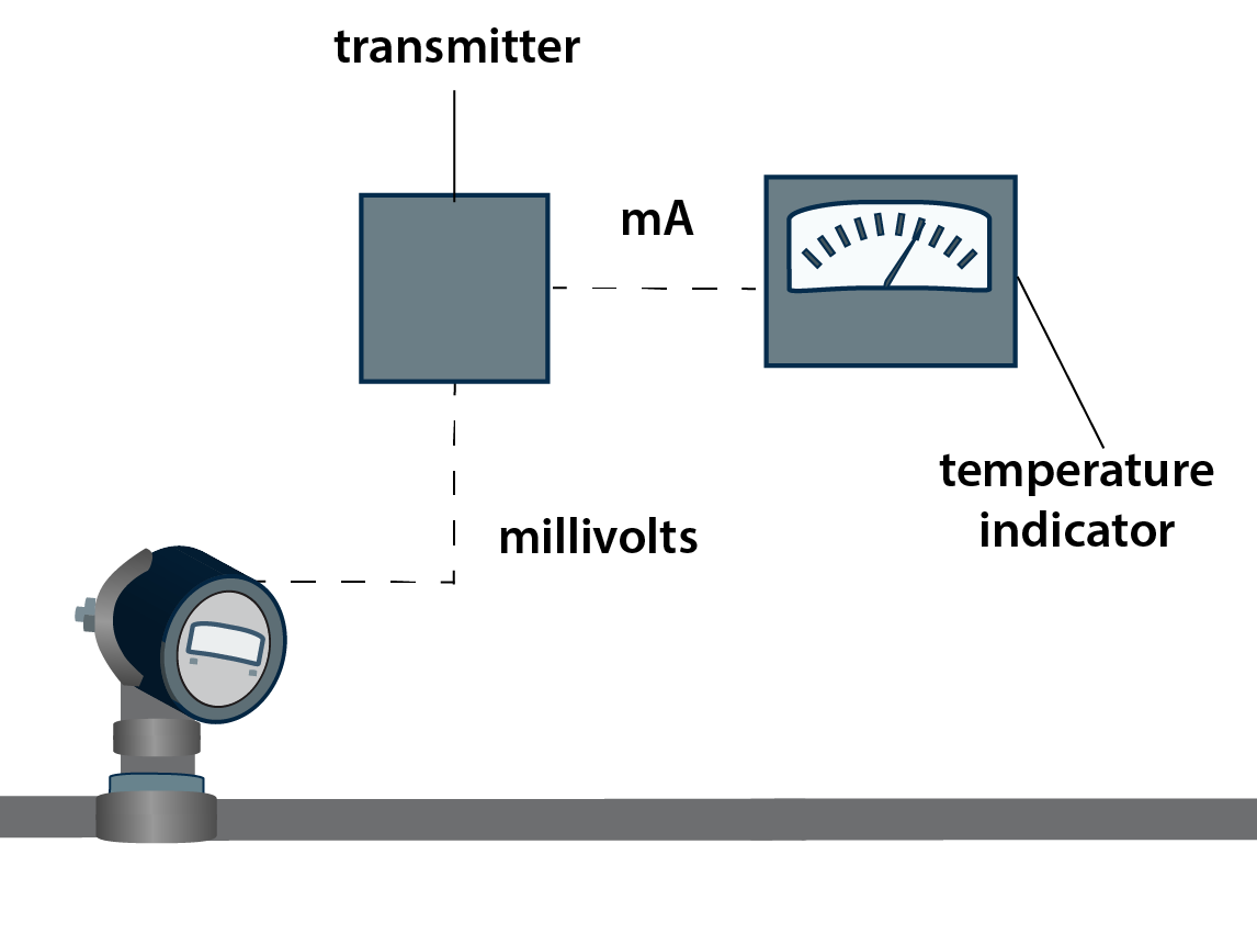
[image 140-9-1]
SPAN, Operating Range
- SPAN = URV — LRV
- Operating Range is ‘LRV to URV’
- Temperature transmitter calibrated for operating range 100 deg F to 400 deg F
- Span = 300 deg F
- Temperature transmitter calibrated for operating range 1500 deg F to 1800 deg F
- Span = ?????
- Transmitter output signal calibrated for operating range 4mA to 20 mA
Transmitter Scaling
- Output of Transmitter represents 0-100% of measured process variable
- 4 mA = 0%
- 20 mA = 100%
Span, %Span
| Percent of Scale | Input | Output |
|---|---|---|
| 0% | 500ºF | 4 mA |
| 25% | 625ºF | 8 mA |
| 50% | 750ºF | 12 mA |
| 75% | 875ºF | 16 mA |
| 100% | 1000ºF | 20 mA |
Scaled Sensor Input – Transmitter Output
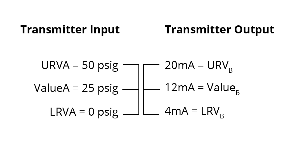
[image 140-9-2]
Transmitters: Input to Output
Transmitter Input vs. Output
(linear)
Where:
A = Original Scale (input)
B = New Scale (output)
LRV = Lower Range Value
URV = Upper Range Value
SPAN = URV – LRV
Sample Scaling Problem: In a standard I/P transducer, an 8-mA input corresponds to what output signal?
Input = electrical signal
Output = pneumatic signal
| Data | Equations | |
| VALUEA | 8 mA | |
| LRVA | 4 mA | |
| URVA | 20 mA | |
| SPANA | 16 mA | |
| LRVB | 3 psig | |
| URVB | 15 psig | |
| SPANB | 12 psig | ValueB = 6 psig |
Scaling Problem : A temperature transmitter uses a thermocouple sensor and is calibrated to 100 deg F — 300 deg F as a 4-20 mA output signal. If the fluid temperature is 200 deg F, what is the output signal in mA?
| Data | Equations | |
| VALUEA | 200 ºF | |
| LRVA | 100 ºF | |
| URVA | 300 ºF | |
| SPANA | 200 ºF | |
| LRVB | 4 mA | |
| URVB | 20 mA | |
| SPANB | 16 mA | Value B = 12 mA |
Scaling Problem: A pressure transmitter is calibrated at 0-300 psig, with an operating setpoint of 175 psig. What is the percent span of the setpoint?
| Data | Equations | |
| VALUEA | 175 psig | Insert Equation |
| LRVA | 0 psig | |
| URVA | 300 psig | |
| SPANA | 300 psig | Insert equation |
| LRVB | ||
| URVB | ||
| SPANB | % Span = 58.3% |
Scaling Problem: A thermocouple has an operating range of 150 deg F – 700 deg F. Current reading is 220 deg F. What is the scaled output from a standard electronic transmitter at this reading?
| Data | Equations | |
| VALUEA | 220 ºF | |
| LRVA | 150 ºF | |
| URVA | 700 ºF | |
| SPANA | 550 ºF | VALUEB = (70/550) x 16mA + 4mA |
| VALUEB | 6.04 mA | |
| LRVB | 4 mA | |
| URVB | 20 mA |
VALUE – 2.04 mA + 4 mA 6.04 mA output signal |
| SPANB | 16 mA |
Example: Pressure transmitter is calibrated to measure from 0-80 psig, and it is measuring 20 psig. What is the output of its standard 4-20 mA transmitter?
VALUEA ?
LRVA?
URVA?
SPANA?
LRVB?
URVB?
SPANB?
Why is I/P one of the most common transducers?
![A diagram of an I/P Transducer [140-10-01]](https://millops.community.uaf.edu/wp-content/uploads/sites/605/2017/03/millops-140-10-01.png)
[140-10-01]
REVIEW/DISCUSSION
Is this control loop open or closed?
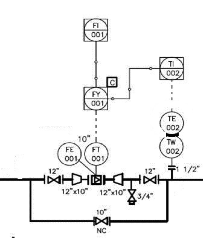
[140-10-02]
| Component | Element Type | PV being controlled or manipulated | Component Function |
|---|---|---|---|
| TW-002 | Thermowell | n/a | Housing the sensor |
| TE-002 | Temperature element | Temperature | Sensing the temperature |
| TI-002 | Temperature indicator | Temperature | Indicating and transmitting the temperature |
| FE-001 | Flow element | Flow | Sensing the flow |
| FT-001 | Flow transmitter | Flow | Transmitting the flow of data |
| FY-001 | Flow transducer or flow computer | Flow/Temperature | Calculation - temperature and flow to calculate net of mass flow |
| FI-001 | Flow indicator (net) | Flow | Indicates the final flow rate |