Contents
Objectives
At the end of this lesson students should be able to:
- Explain the use of rod mills in mineral industry.
- Explain rod mill operation.
- Recognize different design parameters of rod mills.
- Explain problems associated with rod milling.
- Summarize considerations in rod mill selection
Reading & Lecture
Introduction
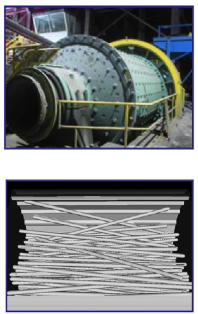
- Used as the primary comminution unit in a grinding circuit.
- Rods are placed parallel along the length of the rod mill.
- Rods are 150mm shorter than the mill length.
- Breakage occurs more from cascading than cateracting.
- The product size distribution is narrower than a ball mill but significantly coarser.
- Most are overflow discharge type.
- Length-to-diameter= 1.4 to 2.3.
- Mill length = 7 meters.
Rod Mill-Ball Mill Circuits
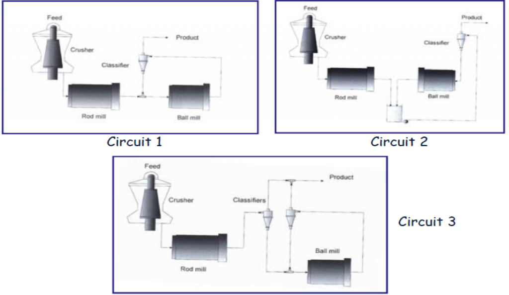
Rod Mill Operations
- Designed to accept feed from a secondary crusher.
- Feed particle size = 6 – 25 mm.
- Peripheral speed = 85- 146 m/min
(280 – 480ft/m in) - Reduction ratio = 2 – 20 depending on material. Typically R = 8.
- Rod Mill Charge:
- Typically 45% of internal volume; 35% – 65% range
- Bed porosity typically 40%.
- Height of bed measured in the same way as ball mills.
- Bulk density of rods = 6.25 tons/m3
- In wet grinding, the solids concentration 1s typically 60% – 75% by mass.
[image: (135-8-3)]
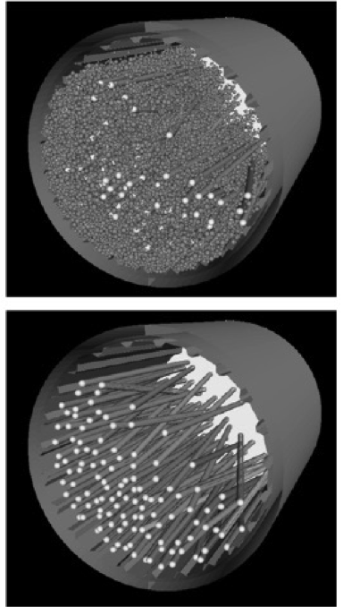
Rod Dimensions
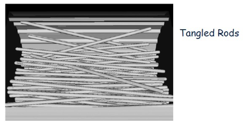
- Rod tangling is a problem that should be avoided by using straight rods.
- Rods < 6 meters are generally never straight.
- Rods should be 152mm shorter than mill length.
- Rod life is maximized of rod length-to-mill diameter is maintained between 1.4 to 1.6.
- Rods wear unequally with thin rod formed at the feed end and forming an elliptical shape.
- Rod diameter is a function of:
- Ore Work Index
- Ore Feed Size
- Ore Density
- Rod diameter can be estimated by the expression (Rowland & Kjos):d↓R = 25.4[F↓80↑0.75 / 160 (W↓iÏ↓S / 100Φ↓C (3.281D) ↑0.5) ↑0.5] mm
[image: (135-8-4)]
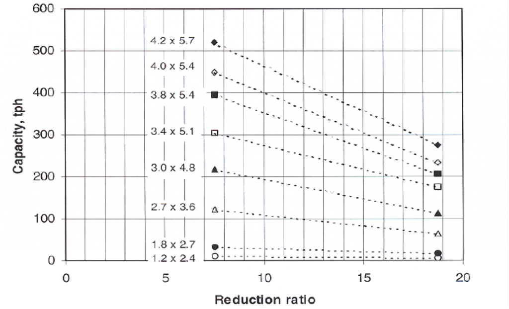
Reduction Ratio
- Reduction ratio ranges from 2 to 200.
- Typical reduction ratio = 8.
- The optimum reduction ratio can be determined from the following expression:R↓0R = 8 + 5L/D
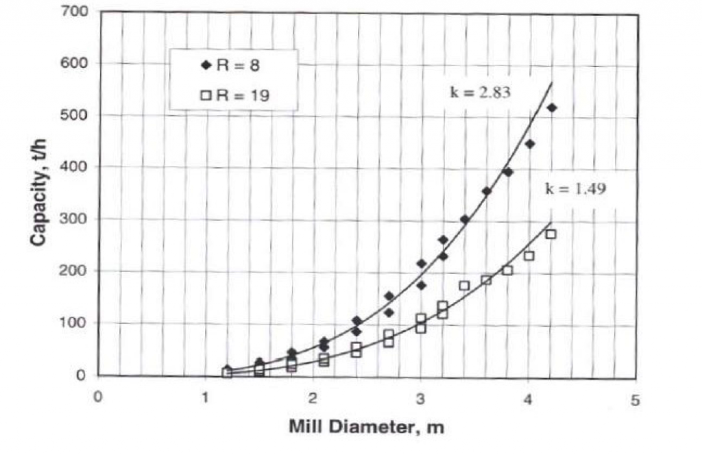
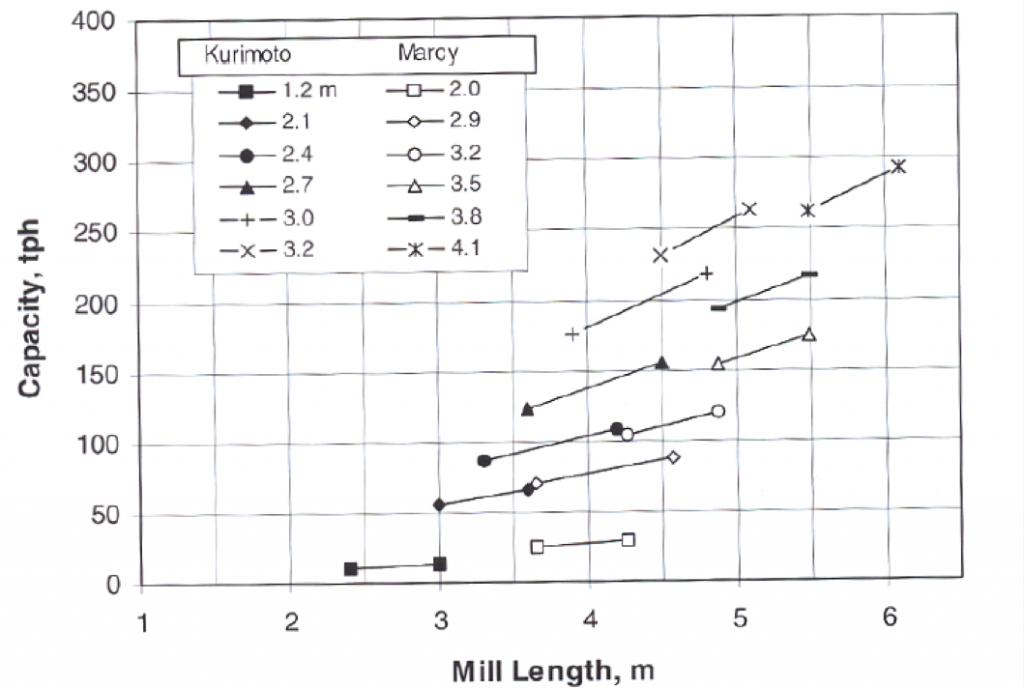
Rod Mill Capacity
Mill capacity is dependent on:
- Mill Characteristics (length, diameter, rotation speed, lifters)
- Feed Characteristics (work index)
- Reduction Ratio
Under given load and particle size requirement, capacity is a function of mill length and diameter:
Q = kLD 2+N
N is related to mill diameter which decreases with larger diameters k a constant equal to π /4.
[image: (135-8-5)]
[image: (135-8-6)]
[image: (135-8-7)]
Rod Mill Capacity Problems
- Difficulty in manufacturing perfectly straight rods.
- Tangling of rods.
- Swelling of the charge near the feed end.
- Increasing slurry density due to loss of water.
- Faulty liners and lifters.
[image: (135-8-8)]
Rod Mill Power Draft
Rod mill power is dependent on mill capacity and work index.
Mill power increases with:
- Increasing rod charge;
- Increasing mill speed;
- Increasing mill length.
Rowland and Kjos (1980) provided an expression to quantify power draw at the pinion shaft per unit mass of rods:
P↓M / M↓R = 1.752 D↑0.33 (6.3 – 5.4J↓R) Φ↓C kW/t
D = mill inside diameter (meters)
JR = fraction of mill volume occupied by rods
Φc = fraction of critical speed.
The Rowland and Kjos equation indicates that power draw is a function of the fraction of the critical speed for the mill.
Marcy mills are recommended to operate a peripheral speeds governed by the following relationship :
Peripheral Speed= 108.8 D0.3 meters/ min
D = mill diameter in meters
The Marcy expression is applicable for mill diameters between 1.52 to 4.1meters.
Using peripheral speed, the rotational speed can be determined.
Bond quantified the rod mill power draw as a function of the Work Index, capacity, and a series of correction factors:
PM = Wmtest,i FT Q
FT = F1 F2 F3 F4 F5 F6
Rod Mill Draft Power Corrections
F1 : Correction for Dry Grinding = 1.1 to 2.0
- For most materials, F1 = 1.3
F2: Correction for Mill Diameter
F↓2 = (2.44 / D) ↑0.2 for D<3.81 meters
= 0.914 for D>3.81 meters
F3: Correction of Oversize Feed
- Austin et al. (1984) defined the need for correction when:
F↓80>4000(14.3/W↓i,test) ↑0.5 - The optimum top size for a rod mill is defined by:
F↓opt = 16000(14.3 / W↓i) ↑0.5 - Correction:
F↓3 – 1+(W↓i / 1.1 – 7) (F↓80 – F↓opt / F↓opt) /R
F4: Correction for Fineness of Grind
F↓4 = P↓80 + 10.3 / 1.145 Ρ↓80
F5: Correction for Reduction Ratio (low or high)
- The correction is not needed if:
-2 < (R – R*) < =2
R↑* – 8 + 5 L↓R / D
Where LR = length of rod in meters
- Correction
F5 – 1 + 0.0067 (R – R*)2
| Condition | Correction |
| Feed prepared by open circuit crushing | 1.4 |
| Feed prepared by closed circuit crushing | 1.2 |