Contents
Hydrometallurgical Processing
[image 145-7-01]
- Milling
- Leaching Metal (Quantity – % Recovery)
- Removal of Metal from Pulp
- Purification (Quality – g/L and removing other ions)
- Electrowinning or Precipitation Followed by Smelting
Why Leaching?
[image 145-7-02]
- Traditional methods viz – ore sieving, washing, etc. are obsolete and uneconomical.
- Pyro-metallurgy is highly costly and non-viable for low-grade ores.
- Leaching is the only process to extract metallic content from the low-grade ores.
- Among leaching methods — Heap leaching is most economical
Basics of Dissolution

[image 145-7-3]
- raw material and its impurities
- chemicals
- recovery degree and rate
- environmental aspects
- money
Dissolution rate can be improved by
- decreasing the particle size
- increasing the temperature
- improving the mass transfer (e.g. stirring)
Lixiviants
Lixiviant is a liquid medium used to selectively extract a desired metal from a bulk material. It must achieve rapid and complete leaching.
The metal is recovered from the pregnant (or loaded) solution after leaching. The lixiviant in a solution may be acidic or basic in nature.
- H2SO4
- HCl
- HNO3
- HCN >> NaCN/KCN
- NH4OH
- NH4Cl or NH4CO3
- NaOH/KOH
Types of Leaching
[image 145-7-4]
[image 145-7-5]
[image 145-7-6]

[image 145-7-7]
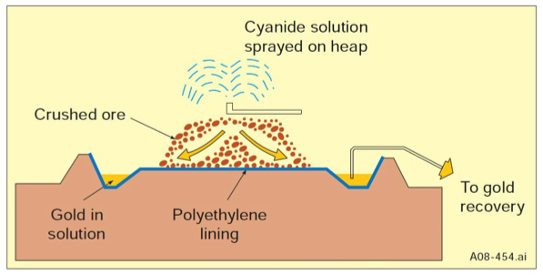
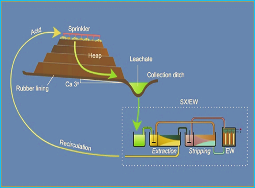
Heap Leaching
- Heap leaching is a simple, low-cost method of recovering precious metals from low-grade ores.
- Ore is stacked in heaps over an impermeable leaching-pad.
- Leach liquid is irrigated at the top
- Liquid reacts with metal and dissolves it.
- Dissolved metal collected at the bottom in the leaching pad.
[image 145-7-8]
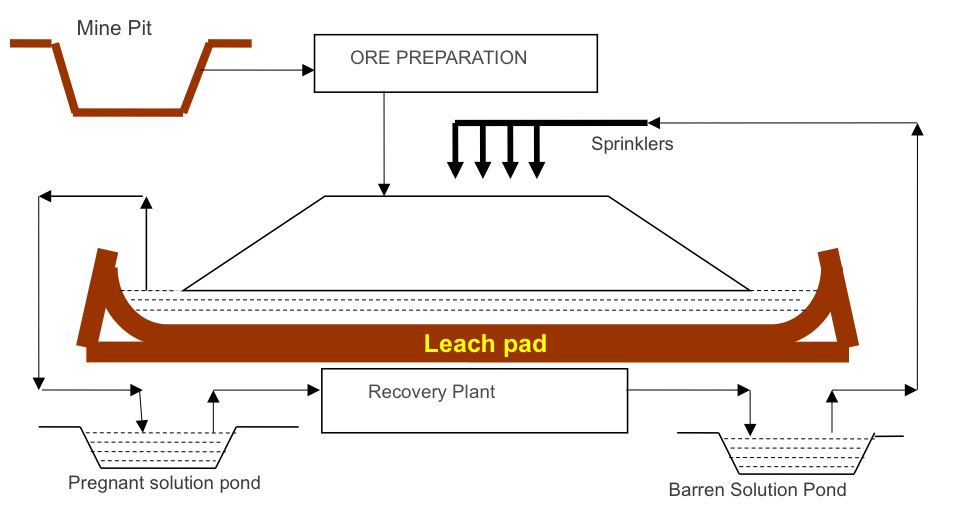
Components of Heap Leach
[145-7-9]
- Impermeable leach pad
- Liners
- Crushed metal ore
- Irrigation system
- Pregnant solution pond
- Barren solution pond
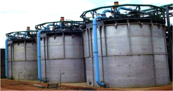
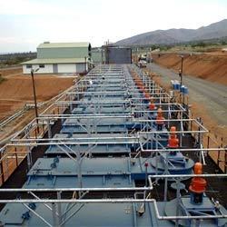
Important Efficiency Factors
- Retention time-total volume of tanks / slurry volumetric flow
- Particle Size-high recovery achieved as liberation increases
- Pulp density-percent solids determines retention time and determines settling rate and viscosity
- Numbers of tanks
- Dissolved gases-Gas is injected below the agitator or into the vat bottom to achieve the desired dissolved gas levels. Typically, oxygen or air, or, in some base metal plants, SO2 is used.
- Reagents-Insufficient reagents reduces metal recovery while Excess reagents increases operating costs and may lead to lower recovery due to dissolution of other metals.
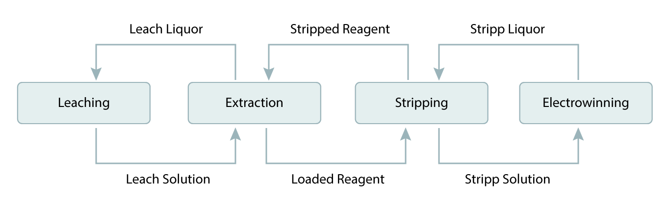
SX – Solvent Extraction
- Pregnant (or loaded) leach solution is emulsified with a stripped organic liquid and then separated
- Metal is exchanged from pregnant solution to organic
- Resulting streams are loaded organic and raffinate (spent solution)
- Loaded organic is emulsified with a spent electrolyte and then separated
- Metal is exchanged from the organic to the electrolyte
- Resulting streams are stripped organic and rich electrolyte
[image 145-7-10]
Electrowinning and electrorefining
- Electrowinning, electrorefining and electroplating involve the exchange of electrons between a solid electrode and ions or molecules dissolved in solution
- The rate of the reaction involved depends on the
- electrode potential,
- electrode area and
- rate of mass transport of the electroactive species to the electrode surface.
- The main differences are in the construction of t he cells, their geometry, construction materials, and operating practice.
Gold Processing
- Gold is usually present as a metal, alloyed with metallic silver and perhaps, copper. The high S.G. (19.3) of gold means that that gold particles, even when of sub-sieve size, settle readily from pulps in which the main gangue mineral is silica.
- Gold is malleable, and during grinding to liberate the gold from associated gangue mineral, the particles of gold become flattened without being reduced in size. This differential grinding effect can assist in the recovery of gold by gravity separation within the grinding circuit itself.
- Against this however, the weight and malleability of gold particles can lead to significant retention in the pump and sump boxes in a closed grinding circuit.
- In addition to “native” gold, the element may occur as inclusions with sulphide minerals such as pyrite, pyrrhotite, stibnite, arsenopyrite, and galena at sizes as small as only 1 micron in diameter.
- Cyanidation for gold recovery is used world-wide for various ore types. The process of Cyanidation proceeds in four stages:
- Preparation of the ore to expose its gold.
- Dissolution of gold using low strength NaCN solutions (0.05%).
- Separation of gold-rich liquid from residual solids.
- Recovery of gold from pregnant solution.
- The gold is recovered from the loaded solution by precipitation with Zn dust in a process known as Merrill-Crowe. This process demands a clarified and de-aerated liquor.
- Today, modern practice utilizes Activated Carbon to strip the gold from solution. This process, known as Carbon-in-Pulp or Carbon-in-Leach can replace the expensive dewatering steps required of conventional methods. Gold is extracted from the carbon using elution with the eluant treated by electrolysis for recovery onto steel-wool cathodes.
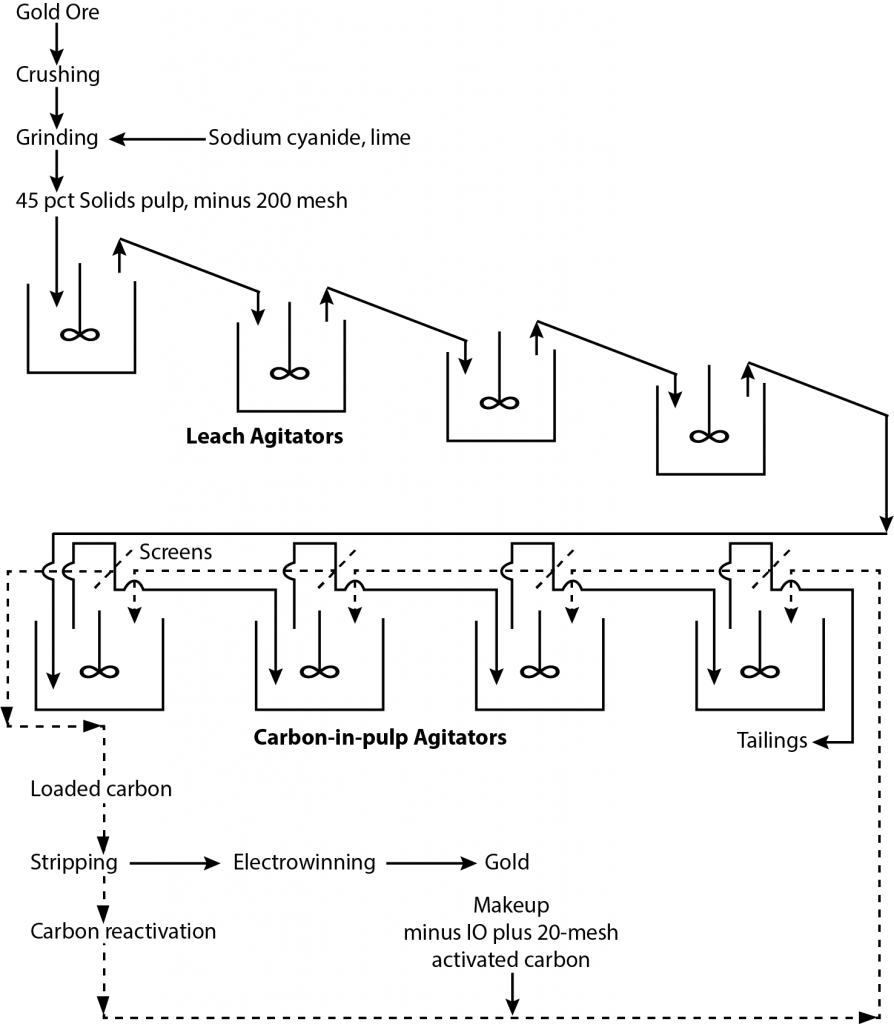
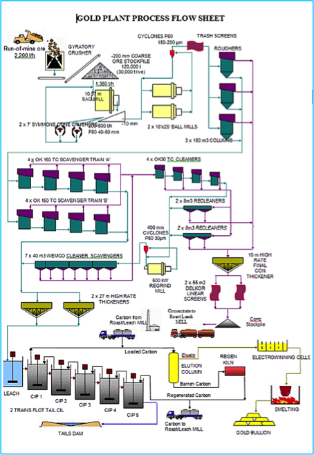
A gold processing circuit
[image 145-7-11] - The major advantage of Carbon in Pulp is not the reduction in the use of zinc dust but rather the impact on the dewatering requirements.
- Using carbon allows the gold to be recovered on coarse pellets (16 mesh) of activated carbon. Activated carbon is made from coconut shells or peach pits to ensure the material is hard and doesn’t abrade during contact with the solid particles in the pulp.
- The carbon is first conditioned to remove sharp corners and to remove fines. Then it is used in the process and recycled through an elution stage. The elution stage removes the gold from the carbon and puts it into a very clean electrolyte solution that goes on for gold recovery by electrowinning.
- The carbon can be reused several times without much loss in effectiveness but eventually the pores become blinded with lime deposits and coatings of organic materials (oils, etc.). So a portion of the carbon is bled off the circuit and sent for regeneration which consists of acid- washing and pyrolysis. Some carbon is burned off and lost but the loss is small and there is no gold associated with the regeneration loss.
