Contents
Objectives
- Define major terms associated with flow and flow measurement
- Identify common types of flow sensing and measuring devices
- Discuss and demonstrate the difference between total volume, flow rate, volumetric flow, mass flow
- Net and Gross Flow (temperature corrections)
- Review P&ID symbols for flow instrumentation
- Demonstrate relationship between dP and flow rate
Reading
Chapters 6 and 7
- Analytical Variables and Instruments
- Miscellaneous Measuring Instruments
Terms to Know
- Reynolds Number, Laminar, Turbulent
- Volumetric Flow
- Mass Flow
- Net and Gross Flow — not in textbook, and important…
- Flow Instrumentation per lecture and notes
Flow — volumetric and mass
- Movement of fluid
- Flow rate = volume/time, or mass/time
- gpm — gallons per minute
- SCFH — standard cubic feet per hour – vapor
- BPD — barrels per day — oil production
- Lbs/hr — pounds per hour
- m/s — meters per second — a velocity value
Reynolds Number
4 factors (Q: What haven’t we given you?)
- Velocity of fluid
- ID of pipe
- Density of fluid
- Absolute viscosity of fluid
LAMINAR flow – < 2,000
Streamlined flow; velocity varies over diameter of pipe
Laminar flow can increase risk of corrosion and scaling — why?

[140-6-1a]
TURBULENT flow – >4,000
Fully turbulent at > 10,000
Fluid flow is consistent, well mixed, usually the desired condition
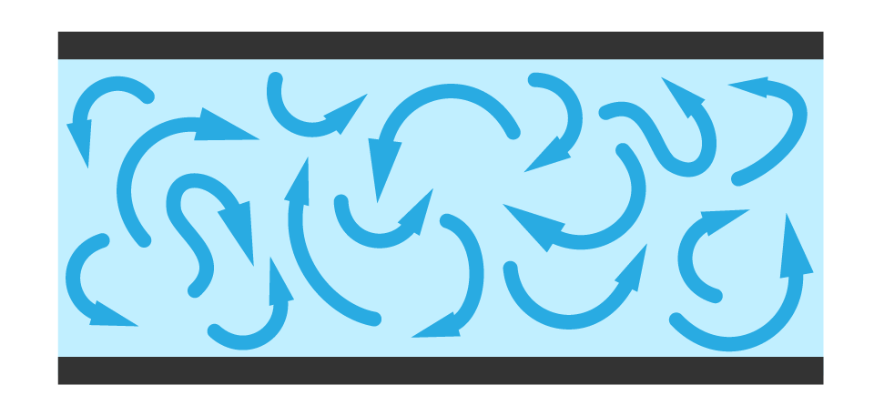
[140-6-1b]
Mass Flow – LIQUID
- Mass/Time (M/T)
- Density = mass/volume = M/V
- Volumetric flow = volume/time = V/T
- Volumetric flow x Density = (V/T) x (M/V) = M/T
- Density varies with temperature, so you need to know the exact density at the flowing temperature to calculate mass
- Balance and convert all units as needed.
Net vs. Gross Flow — LIQUID
(also applies to total volume)
Gross Flow = volumetric flow rate at actual conditions (‘observed’) — what most flow instruments measure
Net Flow = volumetric flow rate converted to flow rate at standard conditions — usually 60 deg F
WHY NET? To keep consistent — measure flow at -20 deg F, then product heats up to 40 deg F — different observed amount of product. You wouldn’t want to keep changing the ‘amounts’ used in records, procedures, designs, sales, etc.
Volume Correction Factors (VCF)
- Need T and VCF to calculate
- VCF — different for each liquid
- Discuss: Why don’t we need P?
- Find VCF for observed T
- Net Flow = Gross Flow x VCF
- Net Volume = Gross Volume x VCF
- Many different types of VCF data — charts, formulas, programs, internal programming in the instrumentation control system
| Temperature | |
| Deg F | VCF |
| 25 | 1.07 |
| 30 | 1.06 |
| 35 | 1.05 |
| 40 | 1.04 |
| 45 | 1.03 |
| 50 | 1.02 |
| 55 | 1.01 |
| 60 | 1.00 |
| 65 | 0.99 |
| 70 | 0.98 |
| 75 | 0.97 |
| 80 | 0.96 |
| 85 | 0.95 |
| 90 | 0.94 |
| 95 | 0.93 |
| 100 | 0.92 |
| 105 | 0.91 |
| 110 | 0.90 |
MASS FLOW, NET FLOW – GASES
- Need both T and P to calculate — why?
- Our old friend — Ideal Gas Law
- Remember: P and T in ABSOLUTE units
P1V1 = P2V2
_____ _____
T1 T2 - Instead of Volume, think volumetric flow: Ft3/hr
Net flow, gas = look at volumetric flow
Condition 1 = observed T, P
Condition 2 = standard T, P
- 14.696 Pounds per Square Inch (psia)
- 60 Degrees Fahrenheit (oF) (520oR)
Use this formula to calculate SCFH from CFH data
Flow Instrumentation
- Direct vs. Indirect Measurement
- Direct measurement — positive displacement
- Sound familiar?
- Very similar to P-D pumps — chamber within meter physically moves a set volume
- Counter tallies the number of times the chamber fills/empties
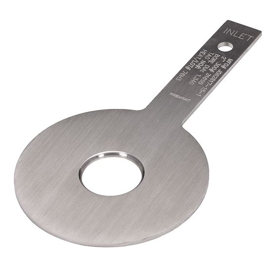
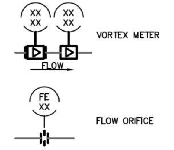
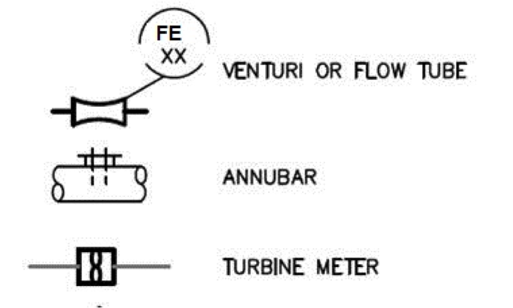
Flow Elements
- Most common indirect measurements use dP
- Orifice Plate, Venturi, Flow Nozzles, Annubar, Pitot
NOTE: These are just the sensing elements — still need some kind of transmitter to create data from the change in dP (differential pressure).
[140-6-2a]
[140-6-2b]
Example Problems
| B | Orifice Plate | A | Measures flow using a tube with several openings and then averaging all flow measures. |
| D | Flow Nozzle | B | Measures flow using a metal disc containing a drilled opening |
| E | Venturi Tube | C | Measures flow using an L-shaped tube and another tube that compares the impinging pressure with static pressure. |
| C | Pitot Tube | D | Measures flow using a tapered inlet device inserted into a flange connection/spool piece |
| A | Annubar ® | E | Measures flow using a cone-shaped device with inlet and outlet components |
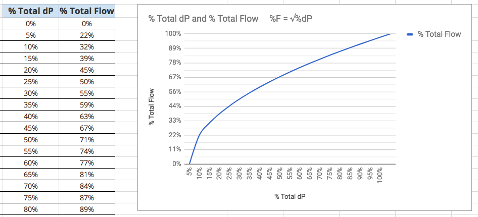
dP vs. Flow
- “Flow rate is proportional to the square root of the differential pressure‘
- Consider the full range of flow and dP that we measure
- Look at % of full range:
- The % of full flow range will vary as the square root of the % of full dP range, or…
- The % of full dP range will vary as the square of the % of full flow range
- %F = √%dP, or
- %dP = (%F)2
- dP = differential pressure through an element
- F = flow rate
- We’ll look at a change in the dP, and a change in the Flow
Example Problems
- 60 % dP
- 60% = 0.60, square root = 0.775
- = 77.5% flow
- 50% dP
- 50% = 0.50, square root = 0.707
- = 70.7% flow
- 45% dP
- 45% = 0.45, square root = 0.671
- = 67.1% flow
- 36% dP
- 36% = 0.36, square root = 0.60
- = 60% flow
% Total Flow vs. % Total dP
%F = √%dP
[image 140-6-3]
% Total dP vs. % Total Flow
%dP = (%F)2
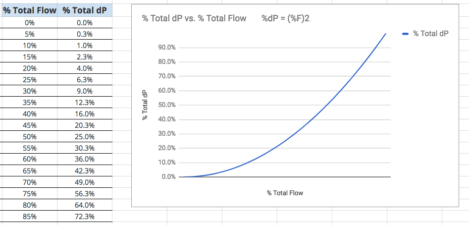
[image 140-6-4]
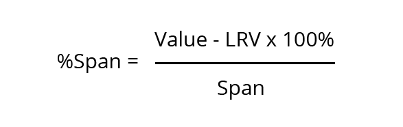
% Span Calculations
- Material covered more thoroughly in Week 10, but we’ve been using it all along.
- Range = the Lower (LRV) and Upper (URV) in the range of the signal, instrument, or process value.
- Example: 4-20 mA signal, the Range is 4 mA (LRV) to 20 mA (URV)
- Span = the difference between the URV and the LRV
- 4-20 mA signal, Span is 16 mA
SPAN, Operating Range
- SPAN = URV — LRV
- Operating Range is ‘LRV to URV’
- Temperature transmitter calibrated for operating range 100 deg F to 400 degF
- Span = 300 deg F
- Temperature transmitter calibrated for operating range 1500 deg F to 1800 degF
- Span = ?????
Scaling – Determining Values for % range
- Scale represents 0-100% of measured process variable
- 4 mA = 0%
- 20 mA = 100%
[image 140-6-5]
Span, %Span
| Percent of Scale | Input | Output |
|---|---|---|
| 0% | 500ºF | 4 mA |
| 25% | 625ºF | 8 mA |
| 50% | 750ºF | 12 mA |
| 75% | 875ºF | 16 mA |
| 100% | 1000ºF | 20 mA |
Scaling: What is %span for operating data?
- Measure operating range — low end is LRV, high end is URV, difference is Span
- Calculate % span through the range:
- Operating valuex = (% desired x Spanx) + LRVx
- Example: What is the 35% point in a temperature scale that reads between 55 and 172 deg F?
- LRV = 55 deg F
- URV = 172 deg F
- Span = 117 deg F (172 F — 55 F)
- (.35 x 117 F) + 55 F = 96 F
Homework problem – %span
- Flowmeter calibrated from 45 gpm — 230 gpm
- Analog signal = 4 mA — 20 mA
- Testing flow rates at listed % span?
- What is LRV, URV, Span of Flow data?
- What is LRV, URV, Span of mA data?
VALUEB = [(% SPANA) x SPANB] + LRVB
Example:
- Value = [(0.14) x 185 gpm] + 45 gpm
- Value = 25.9 gpm + 45 gpm
- Flow Value = 70.9 gpm
- Value = [(0.14) x 16 mA] + 4 mA
- Value = 2.24 mA + 4 mA
- Signal Value = 6.24 mA
Shop Demo — dP vs Flow
- DAC Pump demo unit
- Globe valve to create 3 psi dP in upper spool
- Take readings of flow, dP at the following settings
- Flow at 15 gpm, 12 gpm, 9 gpm, 6 gpm
- What is 100% dP range?
- What is 100% flow range?
- How closely does it follow the calc plan?
Flow Instruments
Rotameter — Fluid flows through the device, lifting a free-floating indicator called a float. The position of the float is referenced to calibrated marks to indicate the flowrate.
Magmeters — Produces a magnetic field that penetrates the flow tube; liquid is the conductor flowing at right angles to the magnetic field. This creates an electrical potential, sensed by electrodes. (voltage)
Flow Instruments — Turbine Meter
- Free-spinning turbine (fan) in flowing liquid-
- The rpm of spinning fan is proportional to flow rate
- Rpm generates a pulse
- Calibrated with the ‘K-factor’ to determine actual flow rate — pulses/gallon
Flow Instruments – Mass Flow
- Coriolis Meter — does not need external compensation for temperature, etc.
- Fluid flows through a vibrating coil — sensors measure the twisting, oscillation, and can calculate velocity, flow, mass, etc. from all this data.
- Video illustrates this principle
- Very powerful tools — lots of data from one instrument.
dP transmitters
- We’ve seen dP transmitters used to calculate dP, level, density — now we can calculate flow
- Uses the Bernoulli principle, and the relationship between dP and flow rate (already discussed)
Vortex Meter
- Common process meter — minimal pressure drop
- The vortex element extends into the process fluid, disrupts flow — creates eddies (vortices) around the ‘bluff body’ of the element
- Sensors pick up the pressure fluctuations caused by these eddies — the even signal is proportional to flow rate (calibrated)
Flow Meters – Drawing Symbols
[140-6-6]
[140-6-7]
PID from homework
What’s happening with these instruments?
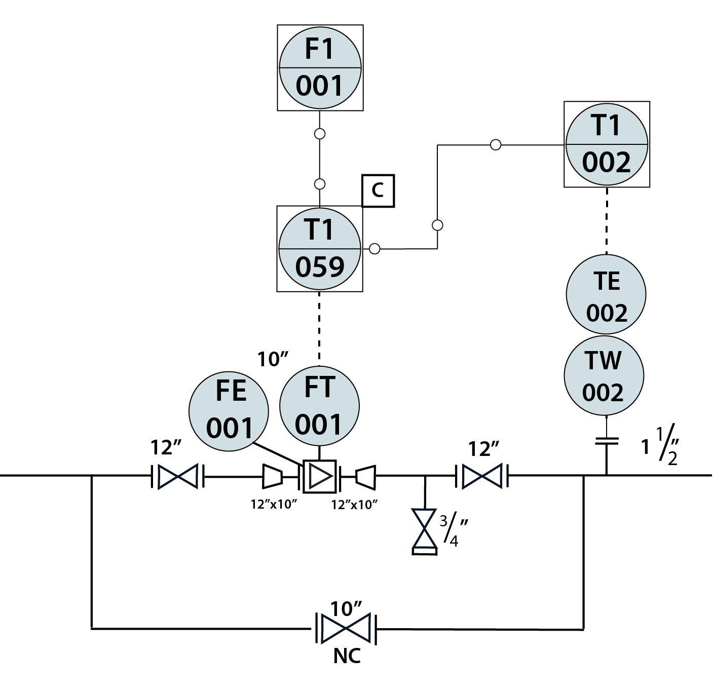
- Why is TE connected to the FY?
- Is this a gas stream or a liquid stream? How do you know?
- What does the C mean?
- What type of flow meter is it?
- What type of TE is it?
- What type of signals are used?
| Tag | Functional Description | Notes |
|---|---|---|
| FE-001 | Flow Element | Note that there is a separate FE/FT drawn. Not always the case. If you draw only one, use the FT |
| FT-001 | Flow Transmitter | |
| FY-001 | Flow Computer | Flow Computer is calculating the mass flow rate using flow and temperature data. The "Y" can indicate different instruments - have to look at the function. |
| FI-001 | Flow Indicator | |
| TW-002 | Thermowell | |
| TE-002 | Temperature Element | Note that this must be a combined TE/TT since it sends a signal. |
| TI-002 | Temperature Indicator |