Contents
Objectives
- Identify components of control valves and regulators
- Describe various operating scenarios
- Discuss valve actuators and positioners
- Explain the ways to reverse controller output signals, and need for such changes
- Describe types of pressure regulator devices
Reading
Terms to Know
- Actuator, Valve Plug, Valve Assembly
- Valve positioner
- Sliding Stem valve
- Butterfly, Ball, Globe, Three-Way valves
- Reverse action — valves and actuators
- Direct action — valves and actuators
- Failure Position — Actuators and Valve Assemblies
- Regulators
Control Valve Components

[Image 140-13-01]
ACTUATOR Action/Failure Positions
[Image 140-13-02]
Air to Open – Fail Down (Closed)
Reverse-Acting Actuator
- Air enters under the diaphragm
- Spring is pushing down
- Air fails = spring pushes all the way down
- Determines position of the valve stem

[Image 140-13-03]
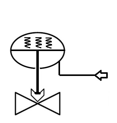
Air to Close – Fail Up (Open)
Direct-Acting Actuator
- Air enters over the diaphragm
- Spring is pushing up
- Air Fails — spring pushes all the way up
- Determines position of the valve stem
ACTUATOR Action/Failure Conditions

mage [140-13-04]
Fail Last
- Electric motor actuators
- Piston actuators
- Double-acting positioners
Action Failure Position – How Do You Know?
- Location of air inlet to diaphragm actuator
- Labeled on the valve in the field
- Labeled on PIDs
- Equipment Data on specific valve
- Overall Valve Failure Position is dependent on the design/operation of both the actuator and the valve (‘valve assembly’)
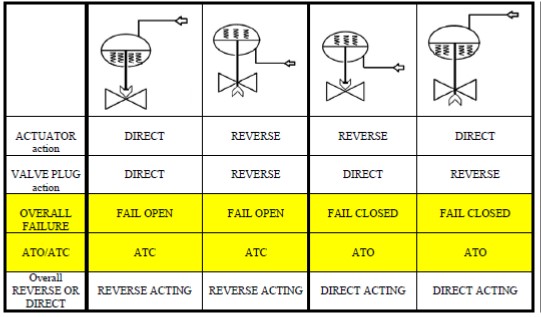
Actuator /Valve Types
- Actuators and valves — both can be Direct Acting or Reverse Acting
- Combination of Actuator/Valve Actions possible:
- Direct/Direct
- Direct/Reverse
- Reverse/Direct
- Reverse/Reverse
Actuators: Action Recap
- Direct Acting:
- Air enters on top of diaphragm
- Increased pressure = extend stem = push down
- ATC on Direct-Acting Valve
- Fail Up (Fail Open on Direct-Acting valve)
- Reverse Acting:
- Air enters underneath diaphragm
- Increased pressure = retract stem = pull up
- ATO on Direct-Acting Valve
- Fail Down (Fail Closed on Direct-Acting Valve)
Actuators – look at detail
Direct Action — Air Extends (pushes down) the Stem – (ATC, Fail Up)
Reverse Action — Air Retracts (pulls up) the Stem – (ATO, Fail Down)
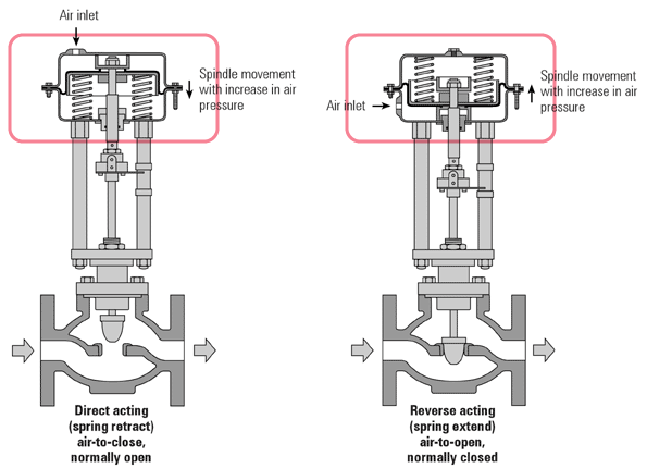
Images [140-13-05+06]
VALVES: Plug Action — New Level of Detail
- Direct Acting = by far the most common
- Push plug down to close
- Closes as stem extends (as stem pushes down)
- ATC with Direct-Acting Actuator
- ATO with Reverse-Acting Actuator
- Reverse Acting =
- Pull plug up to close
- Closes as stem retracts (as stem pulls up)
- ATO with Direct-Acting Actuator
- ATC with Reverse-Acting Actuator
Valve — Direct vs. Reverse Acting
Air Extends (pushes down) the Stem – (ATC, Fail Up)
Air Extends (pushes down) the Stem – (ATC, Fail Up)
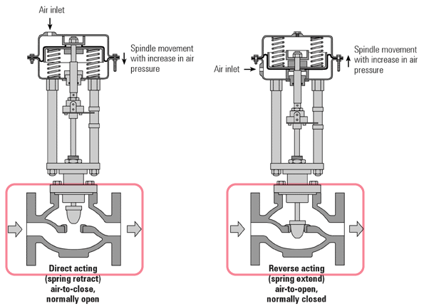
Images [140-13-07+08]
Questions
Why are there different actions for —
- Actuators?
- Failure positions needed
- Control response needed
- Better control of actuator pressure (vs process pressure)
- Control Valve Plugs?
- System pressure
- System fouling
- Push-down-to-close (Direct) is most common
Valve Action Discussion
- Most important?
- Overall Valve Failure Position — FO or FC
- Air to Close (ATC) or Air to Open (ATO)
- Next Importance
- Actuator Direct (Air on Top) — “Fail Open’
- Actuator Reverse (Air on Bottom) — “Fail Closed’
- Next Importance
- Valve Plug Direct (push down to close) — almost all valve plugs are direct. Actuator Failure = same as Overall Valve Failure. If Actuator failure doesn’t match Overall Valve Failure — then look at valve plug action
- Valve Plug Reverse (pull up to close)
Activity
A direct acting controller sends a standard pneumatic signal to a control valve. The control valve has a direct-acting actuator, and the valve itself is reverse-acting. Fill in the information in this table:
| Controller output, % of span | Action dir/rev (if known) | 0% | 25% | 50% | 75% | 100% |
|---|---|---|---|---|---|---|
| Controller output, % in psig | ||||||
| Stem Position - "all the way up" to " all the way down" (depending on the actuator action) | ||||||
| Valve % open, or "fully open" to "fully closed" - (depending on the plug action) |
Check your answers on this table.
Pneumatic Actuators
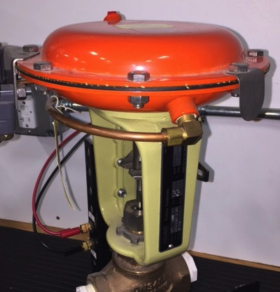
Piston Actuators
note that they can be hydraulic or pneumatic
Piston actuator diagram [image 140-13-13]
Valve Positioners
- Positioners — make the valve position match the controller output signal
- Position the valve
- Reverse the action
- Mimic a valve trim type —
- not discussed much here
- Provide split range control —
- if valve must respond to only part of the signal
- How to Reverse the Controller Output signal
- Can be changed at the I/P transducer
- Can be changed at the Valve Positioner
- Physically reconfigured to respond in reverse
- NOTE: Actuator will still fail in position dictated by spring/air configuration
- Why would you do these reversals?
Valve positioner diagram [image 140-13-14]
Activity
The tag on a pneumatically actuated control valve identifies it as air-to-open. If the positioner has been configured to reverse the signal, then the valve will fail _____________ on loss of instrument air supply.
A. Open
B. Closed
C. In its last position prior to the loss of air
D. None of the above
Types of Control Valves
- Globe
- Three-Way
- Butterfly
- Ball/Segmented Ball
Three Way Control Valve
- Three ports
- Mixing or diverting
- As plug moves, one inlet closes while the other opens
[image 140-13-15]
Butterfly Control Valve
- Higher flow capacity
- Rotary stem/motor
- All types of fluids
[image 140-13-16]
Ball, Segmented Ball Control Valve
- Rotary valve
- Spherical plug
- Segmented has shaped plug — flow characteristics
- Used in slurries
[image 140-13-17]
Air Regulators
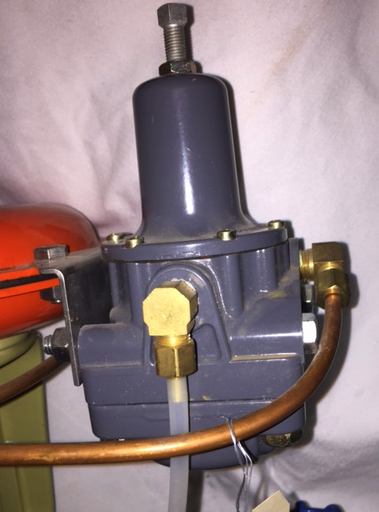
Symbols for Mechanical Regulators
- Note: small regulators on actuators, control valves are not normally shown on PIDs
- In-line mechanical pressure regulators are shown:
- Note direction of the angled line —
- Indicates whether pressure is controlled upstream or downstream of valve…

[Image 140-13-21]
PID, PFD, Symbol Information
- PIDs, PFDs will indicate 3-way valves
- PIDs will normally indicate FO, FC of overall valve
- Will not be specific about actuator vs valve action
- If you need to know that, where do you look?
- PFD will probably not show FO, FC