Contents
Objectives
- Describe Process Control
- Explain the function of a control loop
- Compare “Closed Loops’ and “Open Loops’
- Identify the components of a control loop
- Describe signal transmission types
Reading
Terms to Know
- Setpoint
- Open Loop, Closed Loop, Feedback
- Control, Measure, Manipulate
- Sensor, Transmitter, Controller, Transducer, Final Control Element
- Live Zero
- Loop Error
What is Process Control?
“The act of regulating one or more process variables so that a product of a desired quality can be produced’
How to control a process variable?
- sense/measure it
- compare to the desired value, ‘setpoint’
- calculate necessary change — the error
- make the change — correction
Variables
Controlled — sense this value to initiate signal
Measured — determine actual condition of variable
Manipulated — adjust a quantity or condition
Not always the same process variable — not always the same process stream.
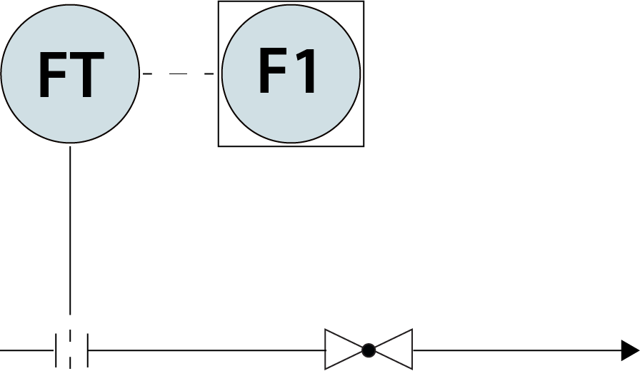
OPEN LOOP
- Instrument provides data
- No connection to the change in the process — someone has to open/close the valve
- No ‘feedback’
- “Manual’ mode
[image 140-8-01]
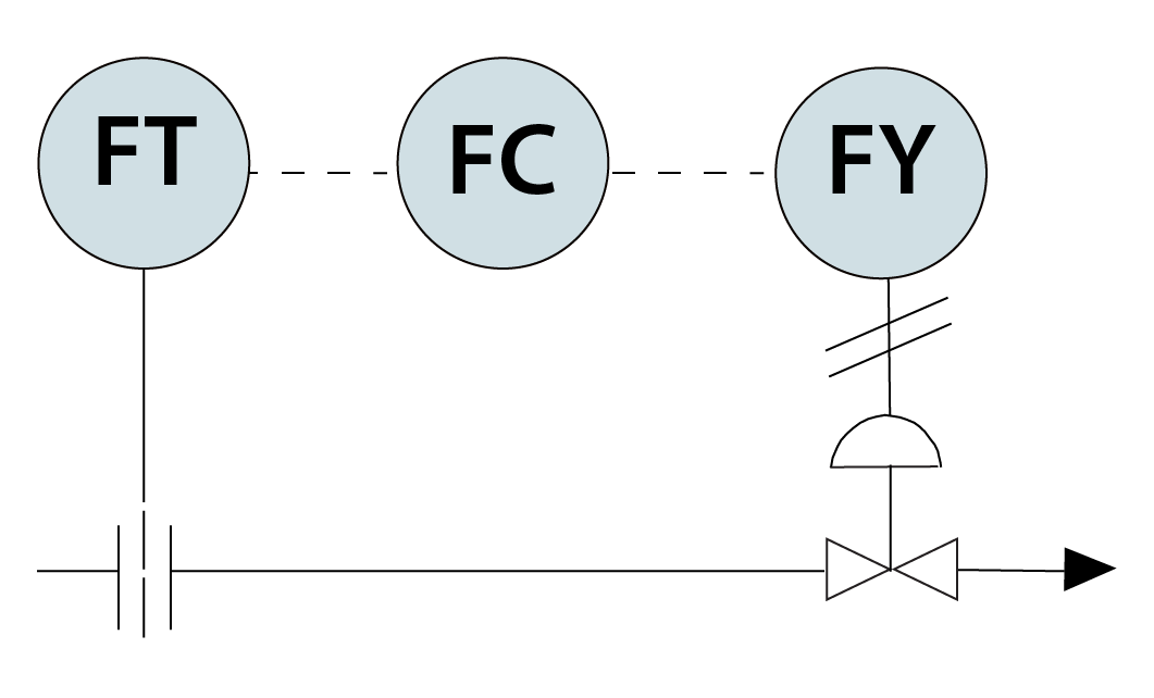
CLOSED LOOP
- Instrument provides data, and also determines the necessary corrections to make
- Instruments control the valve position
- ‘Feedback’ — as level changes, control loop will register the change, and valve position will change as needed
- “Automatic’ mode
[image 140-8-03]

[image 140-8-5]
Control Loop – Components
| Sensor | Sensing |
| Transmitter | Converting, Transmitting |
| Controller | Compare, Calculate, Correct |
| Transducer | Converting (signal type) |
| Final Control Element | Manipulating |
| Also: | |
| Indicator | Displaying (values) |
| Computer | Calculating, Converting |
Sensor (FE, TE, PE, LE, etc)
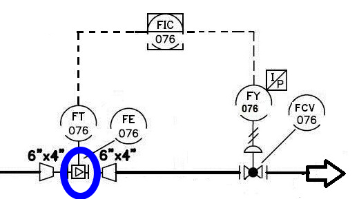
[Image 140-8-06]
Transmitter (FT, TT, PT, LT, etc)
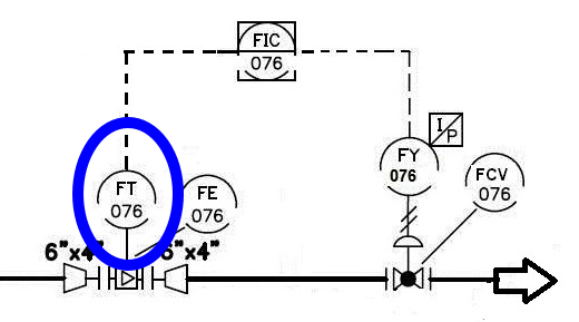
[image 140-8-7]
Controller (FC, TIC, PC, LIC, etc)
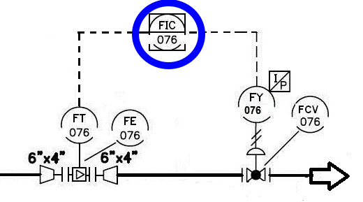
[Image 140-8-8]
Transducer (FY, TY, PY, LY, etc)
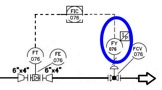
[Image 140-8-9]
Final Control Element (FCV, etc…)

[Image 140-8-10]
Signal Types
- Pneumatic — gas std. 3-15 psig
- Electronic — analog signal std. 4-20 mA, 1-5 VDC
- Often uses the same wires that provide power to instrument
- Digital — binary — computerized — no std. range
- Mechanical — physical linkage — no std. range
Signal Types on PID’s – Recap
Identify the analog electrical, digital, and pneumatic signals in this loop:
[image 140-8-11]
LIVE ZERO — Why isn’t 0 just 0?
- 3-15 psig, 4-20 mA, 1-5 VDC — why not 0-12, 0-16, 0-4?
- If 0 is 0, how do you tell the difference between a reading of 0 and a dead transmitter?
- If 0 is 0, how do you handle any values <0?
- How do you calibrate <0?
- Remember that the range of an instrument is not necessarily 0-something — usually has a LRV and URV, so 0 doesn’t enter into it.
Control Loop Error
- Each component in the loop has an error factor.
- Cumulative error = Loop Error
- Eloop = √[(E1)2 + (E2)2 + (E3)2 …(En)2]
- Where E1, E2, …En = errors of all components in the loop.
Sample Problem, Loop Error
A control loop is composed of a transmitter (accuracy 0.5%); controller (accuracy 0.25%); I/P Transducer (accuracy 0.5%); and control valve (accuracy 1.5%).
- Error = √[0.52 + 0.252 + 0.52 + 1.52]
- Error = √[0.25 + .0625 + 0.25 + 2.25]
- Error = √[2.8125]
- Error = 1.68%
Accuracy calculation
[(measured value — true value)/(true value)] x 100%“Accuracy’ is usually expressed as “accurate +/- x%’.
It doesn’t matter if the value from the calculation is positive or negative…
Sample Problem, accuracy:
Pressure gauge true value is 100 psig, and it is reading 98 psig
- [(98-100)/100] x 100%
- [-.02] x 100%
- -2%
- Gauge is accurate +/- 2%
Loop Analysis procedure…
- List all instruments, full tag numbers
- Start at the sensing element, move through the loop to the final control element
- ‘Variable being controlled’ = variable being controlled OR manipulated
- This variable changes as you move through a loop
- Control Valves almost always manipulate FLOW
Flow Control Loop
Discuss components with class

[image 140-8-12]
| Component | Element Type | PV being controlled | Component Function (table 8-1) |
|---|---|---|---|
| FE-100 | Flow element | Flow | Sensing |
| FT-100 | Flow transmitter | Flow | Convert/Transmit |
| FC-100 | Flow controller | Flow | Compare/Calc/Correct |
| FY-100 | Flow transducer | Flow | Convert signal |
| FCV-100 | Flow control valve | Flow | Manipulating |
Level Control Loop
- Discuss components with class
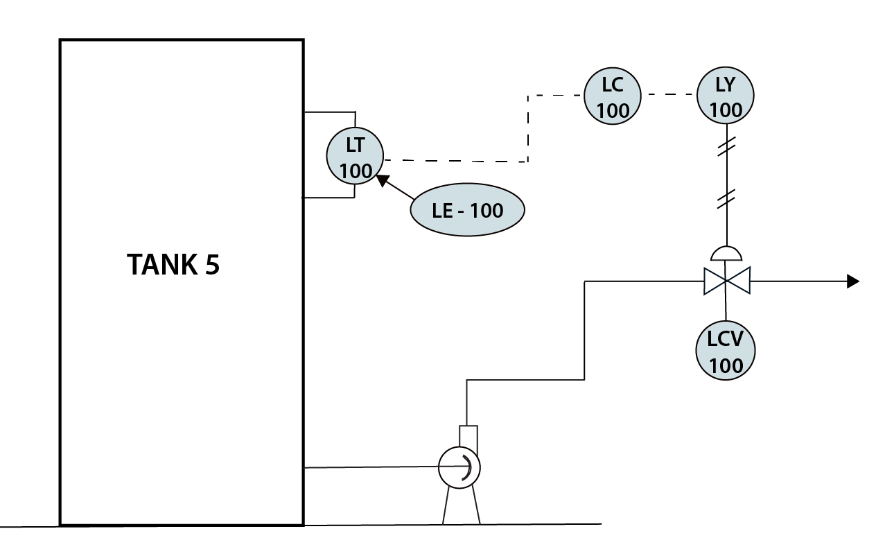
| Component | Element Type | PV being controlled | Component Function (table 8-1) |
|---|---|---|---|
| LE-100 | Level element | Level | Sense |
| LT-100 | Level transmitter | Level | Transmit/convert |
| LC-100 | Level Controller | Level/Flow | Compare/calc/correct |
| LY-100 | Level transducer | Flow | Convert signal |
| LCV-100 | Level control valve | Flow | Manipulate |
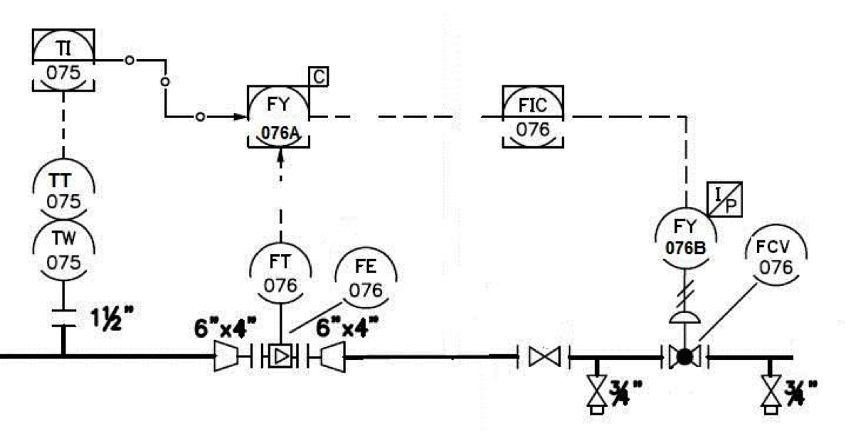
Temperature Control Loop –
- Discuss components with class
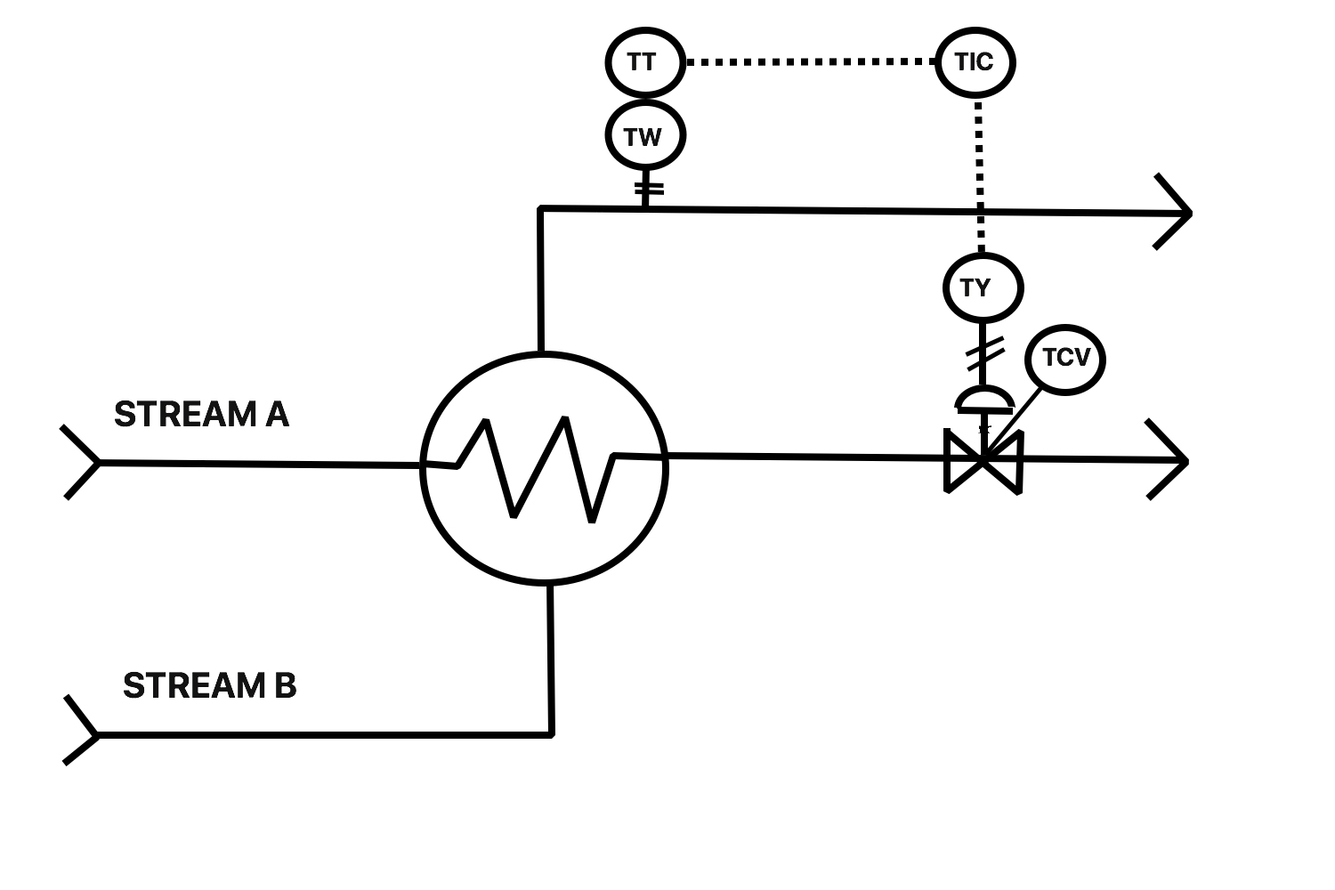
[Image 140-8-16]
| Component | Element Type | PC being controlled | Component Function (table 8-1) |
|---|---|---|---|
| TW | Thermowell | N/A | Protecting |
| TT | Temperature Transmitter | Temperature | Sensing/Convert/transmit |
| TIC | Temperature Indicating Controller | Temperature/flow | Compare/calc/correct/display |
| TY | Temperature transducer | Flow | Convert signal |
| TCV | Temperature control valve | Flow | Manipulate |