Contents
Reading
Gravity Concentration Ratio (CC)
CC = SG of heavy mineral – SG of fluid/SG of light material – SG of fluid
| Concentration Criteria | Suitability for Gravity Separation |
|---|---|
| CC > 2.5 | Easy down to 75 microns |
| 1.75 < CC < 2.5 | Possible down to 150 microns |
| 1.5 < CC < 1.75 | Possible down to 1.7mm |
| 1.25 < CC < 1.5 | Possible down to 6.35mm |
| CC < 1.25 | Impossible at any size |
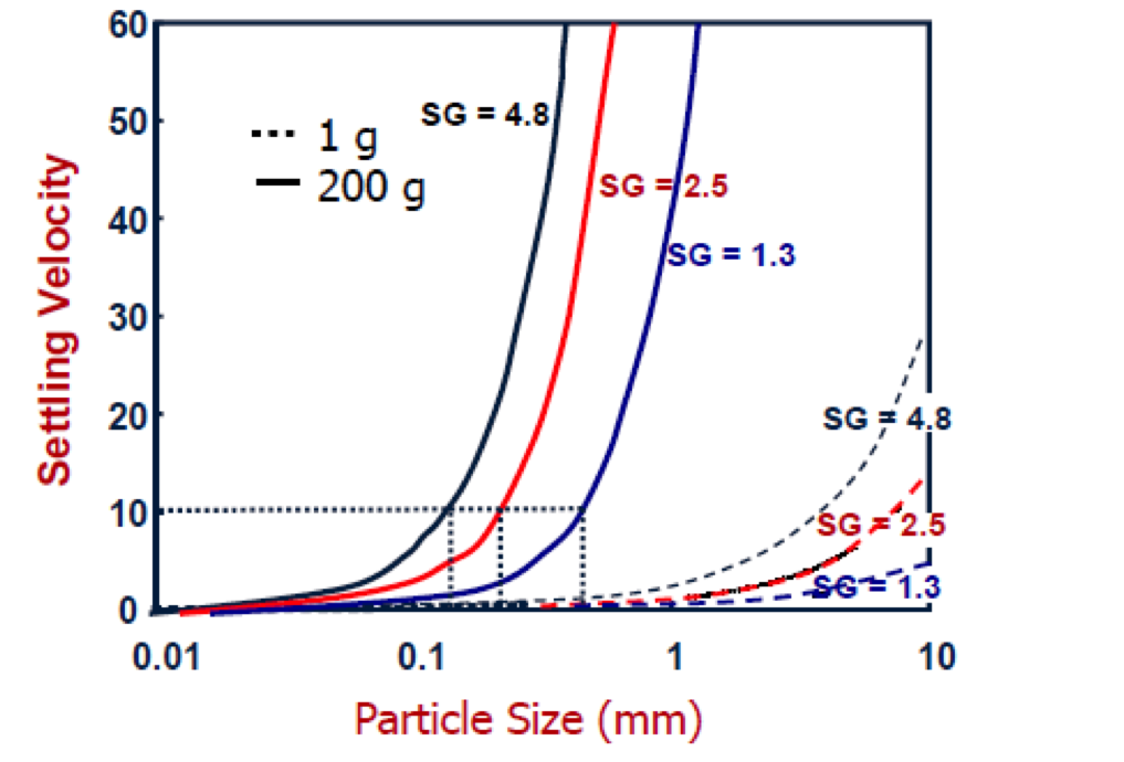
- Reflects the difficulty in separating particles of near density and ultra-fine particles.
- New technologies have enabled density-based separations at finer particle sizes.
Concentration Ratio Examples
CC = SG of heavy mineral – SG of fluid/SG of light material – SG of fluid
| Mineral | Fluid | CC |
|---|---|---|
| Gold | Water | 10.3 |
| Gold | Air | 6.8 |
| Cassiterite | Water | 3.5 |
| Coal | Water | 3.4 |
| Hematite | Water | 2.5 |
| *Gangue material SG = 2.65 | ||
Separation by Differential Setting Velocity
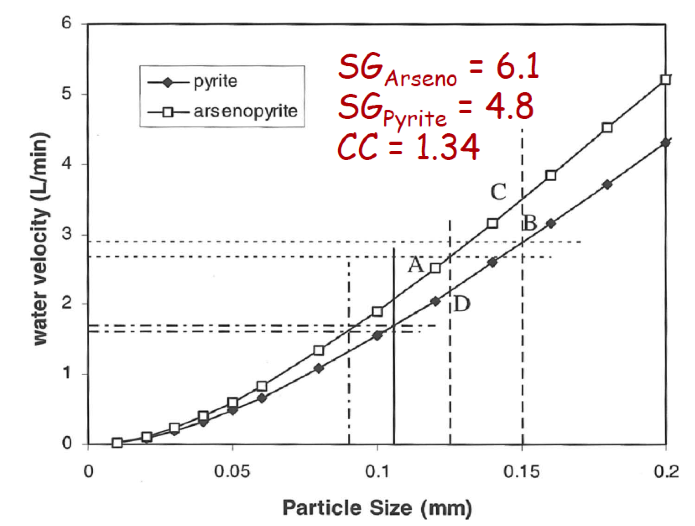
[image 145-4-0]
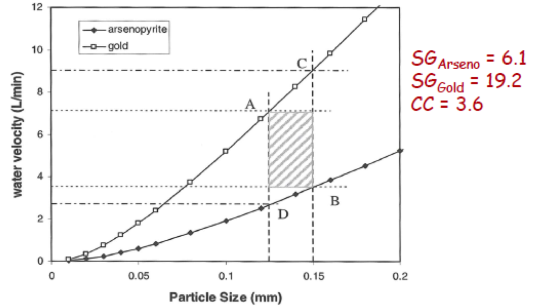
[image 145-4-1]
Daniels Dense Separators
CC = SG of heavy mineral – SG of fluid/SG of light material – SG of fluid
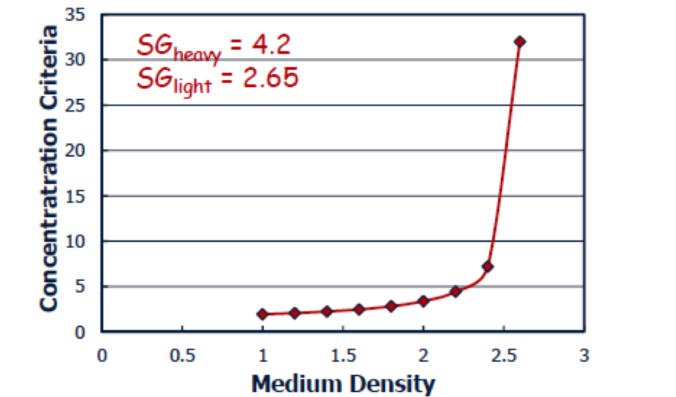
[image 145-4-2]
Viscosity Limits on Medium Type
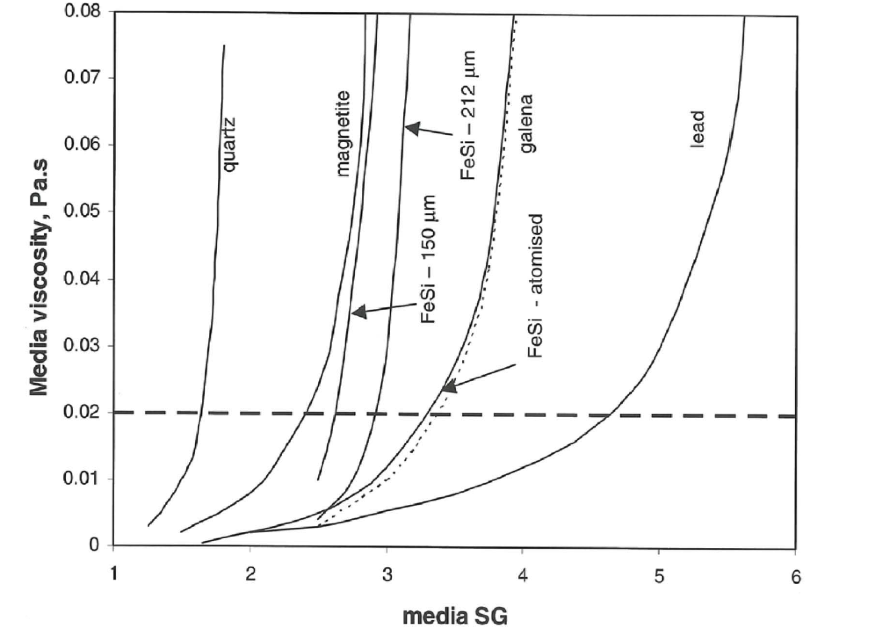
[image 145-4-3]
Heavy Medium Separation Mineral Applications
| Operator/Plant Location | Mineral Processed | Size Range | Plant Feed tph | HMS Units | Sink/Float Ratio | Separation Density |
|---|---|---|---|---|---|---|
| Aluminum Co. od Canada, Ltd. St. Lawrence, Newfoundland | Flourspar Barites | -3/4" + 20M | 80 | 2-15" | 40/60 | 2.72 |
| Barton Mines North Creek, NY | Garnets | -1/4" + 45M | 60 | 1-12" &1-9" | 60/40 | 3.2 |
| Basics Inc. Gabbs, NV | Magnesite | -3/8" + 20M | 30 | 1-9" | 75/25 | 2.9 |
| Bethlehem Steel Corp. Icomi Mine, Amapa, Brazil | Manganese | -1/4" + 20M | 130 | 2-15" | 80/20 | 2.9 |
| Cia. Minera de Autlan S.A. Autlan, Mine | Manganese | -20mm +1mm | 90 | 1-18" | 70/30 | 2.95 |
| Universe Tankships Inc. Para, Brazil (Jari, Project) | Bauxite | -3/8" | 18 | 1-9" | 95/5 | 2.3 |
| Companhia Mineira do Lobito Jamba Mine, Angola, Africa | Iron | -1/4" + 20M | 400 | 6-15" | 80/20 | 2.7 |
| Dresser Minerals Ryder Point Plant | Flourspar Barites | -25mm +1mm | 80 | 2-15" | 50/50 | 2.75 |
| Fundy Gypsum Co. Ltd Windsor, Nova Scotia | Gypsum Rock | -3/4" + 20M | 80 | 2-15" | 30/70 | 2.5 |
| International Mining Co. Enramada Mine, Bolivia | Tin/Tungsten | -1" + 20M | 30 | 1-12" | 25/75 | 2.95 |
| Lithium Corp. of America Bessemer City, NC | Lithium | -1/4" + 65M | 65 | 1-15" | 30/70 | 2.8 |
| NL Industries Inc Guatemala | Scheelite | -1/2" + 14M | 10 | 1-9" | 60/40 | 2.7 |
| Renison Ltd. Zeehan, Tasmania | Tin | -1/2" + 28M | 80 | 2-15" | 80/20 | 3.0 |
| Southern Peru Copper Corp. Ilo, Peru | Coquina Shells | -1/4" + 30M | 50 | 1-15" | 50/50 | 2.7 |
| Turk Maadin Sirketi Beyoglu, Turkey | Chrome | -1/4" + 20M | 10 | 1-9" | 60/40 | 2.9 |
Emeralds Processing by Heavy Medium
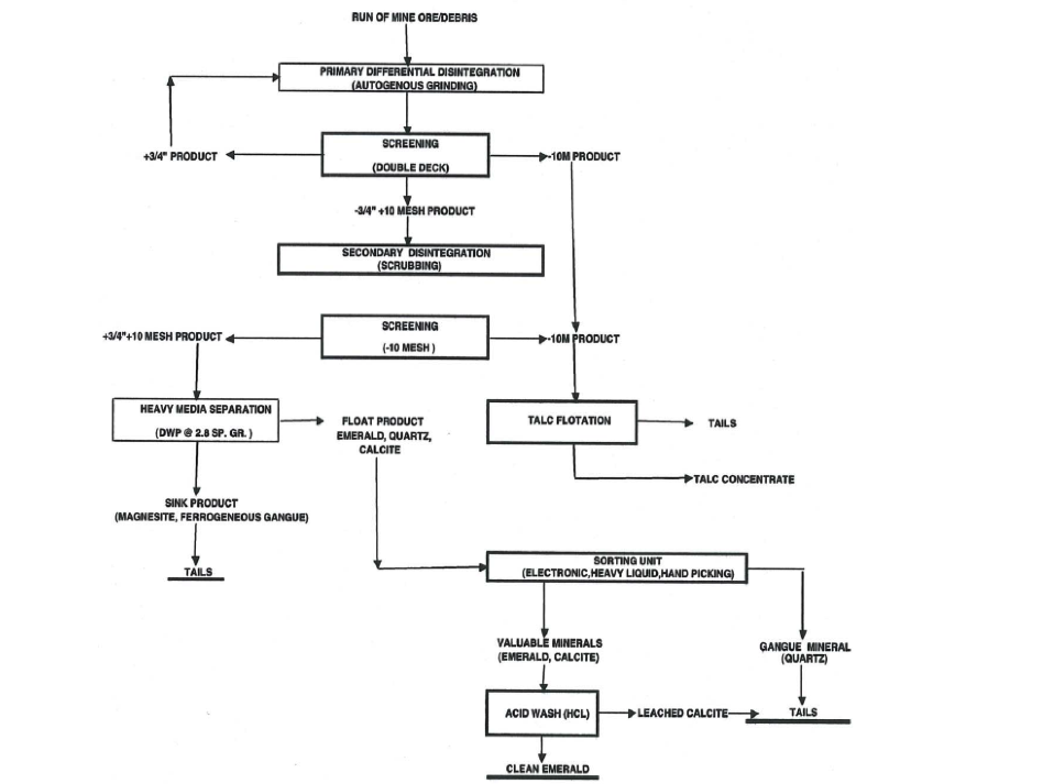
[image 145-4-4]
Jigging Principles
Jigging uses a pulsation of a fluid at a given frequency and amplitude to induce a separation based on differential acceleration, hindered settling and consolidated trickling.
For small particles, short pulsations are preferred to emphasize separation based on differential acceleration.
- Particles in a mixed pile before laying
- Rising water level lifts the bed layer
- Particle sedimentation stratification in the water
- The water level drops, the bed layer is dense, and the heavy mineral settles at the bottom
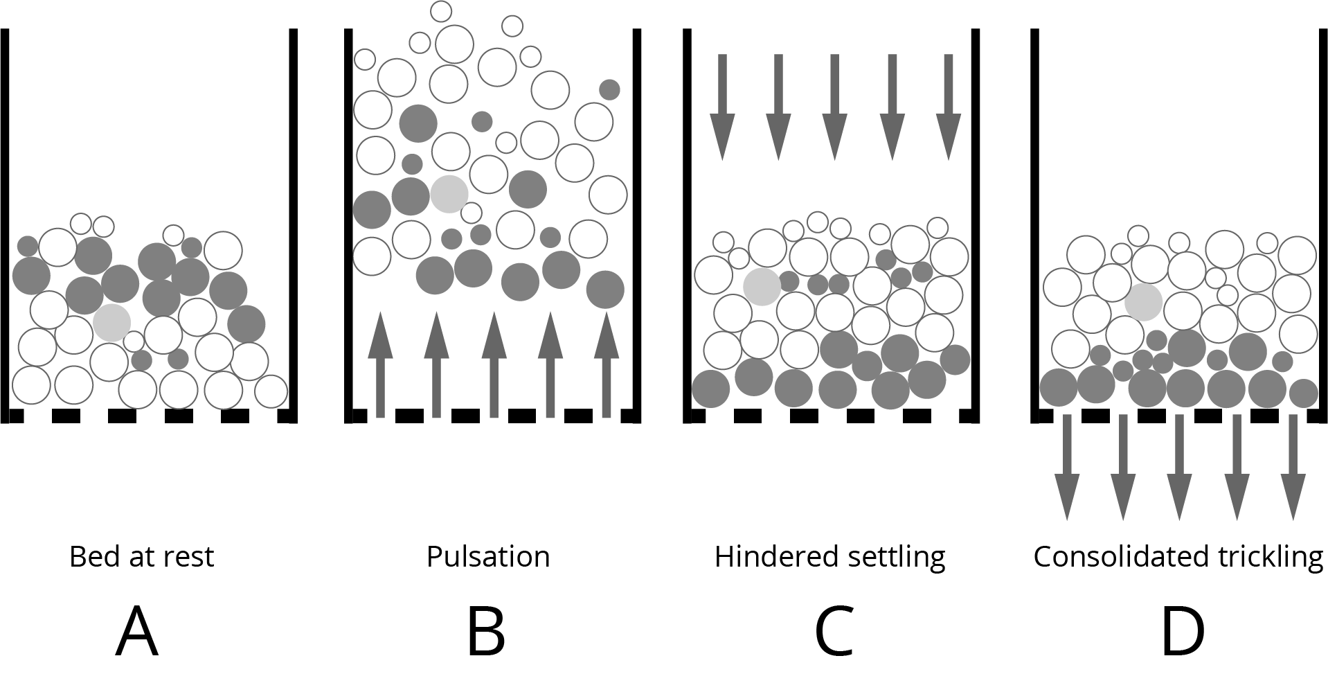
[image 145-4-5]
Jig Types
[145-4-7]

[145-4-7b]
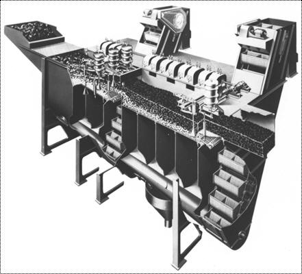
Industrial Jig
[image 145-4-8]
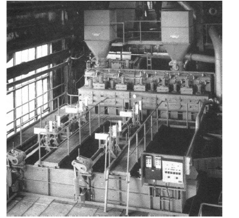
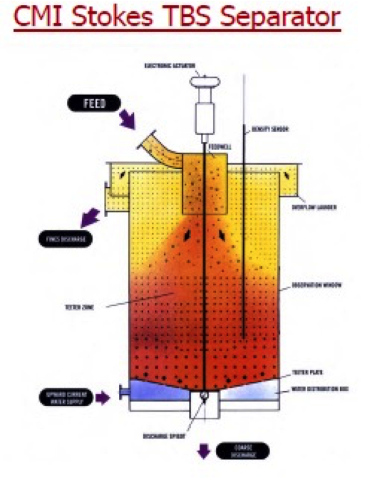
Teeter Bed Separators
Utilizes an upward current of water that has a velocity equal to the high-ash content particles thereby creating a fluidized particle bed.
The bed level is monitored and control by measuring the bed pressure and manipulating the underflow discharge valve.
To report to the underflow stream, the particles must have a density or total mass that can overcome the hindered settling conditions in the fluidized particle bed.
As such, Teeter-Bed units are commonly referred to as autogenous dense-medium devices.
3:1 particle size range.
[image 145-4-10]
- Typical throughput capacity of around 1.0 — 2.0 tons/hr/ft2.
- Previous studies have indicated the ability to achieve efficient density-based separations over a range of medium densities.
- Concern is the bypass of coarse, light particles to the underflow.
- Benefits include a large feed capacity which would eliminate distribution needs.
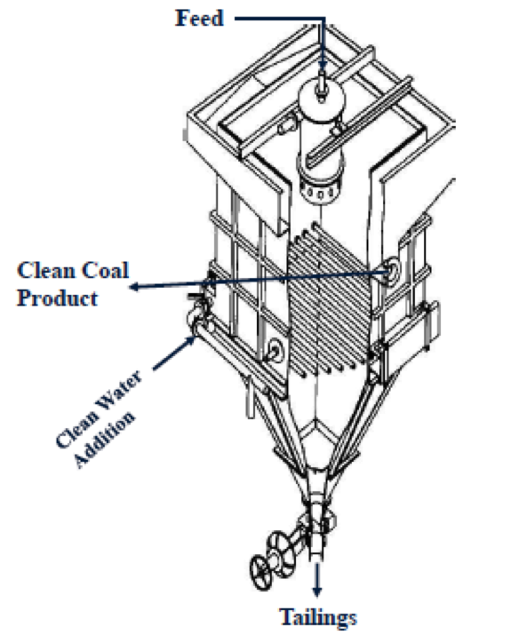
- Commercial units:
- Stokes Hydrosizer
- Crossflow Separator
- Reflux Classifier
- Floatex Classifier
[145-4-11]
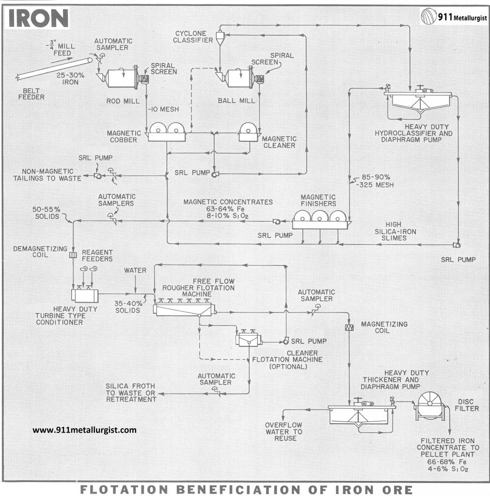
Iron Ore Processing Circuit
[145-4-12]
Iron Ore Processing Using Teeter-beds
| First Stage Separation | Second Stage Separation | Third Stage Separation | |
|---|---|---|---|
| Capacity (t/h) | Nom. 216 Max. 246 Min. 186 | ~132 | ~52 |
| Degree of Enrichment | ≥64.5% Fe | ≥68% Fe Or 68% in total over the two stages |
|
| ≤0.15% P | |||
| ≤1.0% SiO2 | |||
| Iron Recovery (Each stage) | ≥81% | ≥80% | ≥61% |
| Iron Recovery (Compared to incoming Fe-content) | ≥83% | ||
| Solids concentration in underflow (% by weight) | ≥79 | Average ≥76 | |
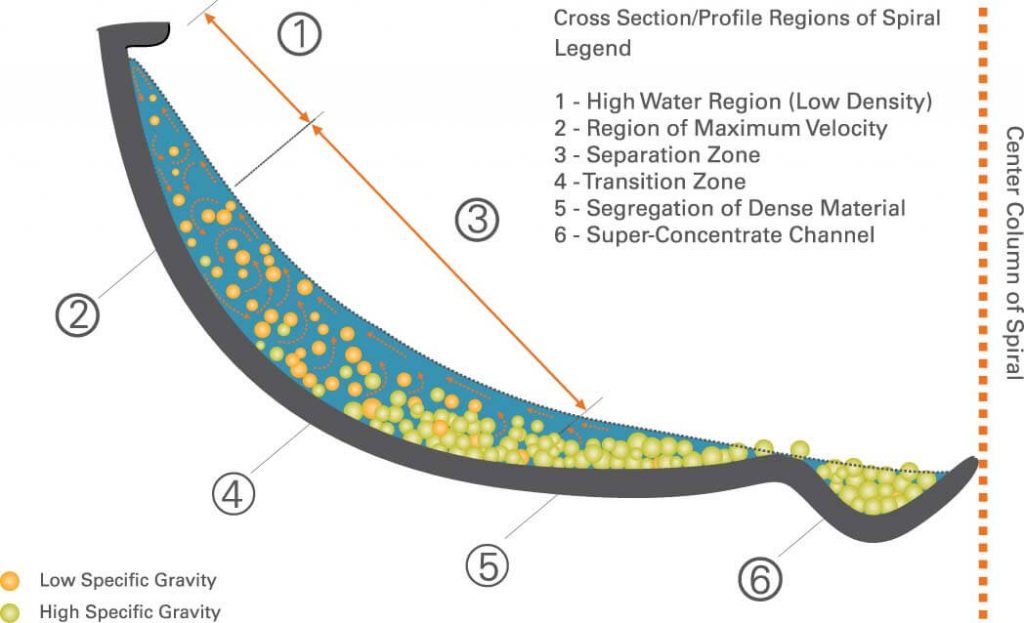
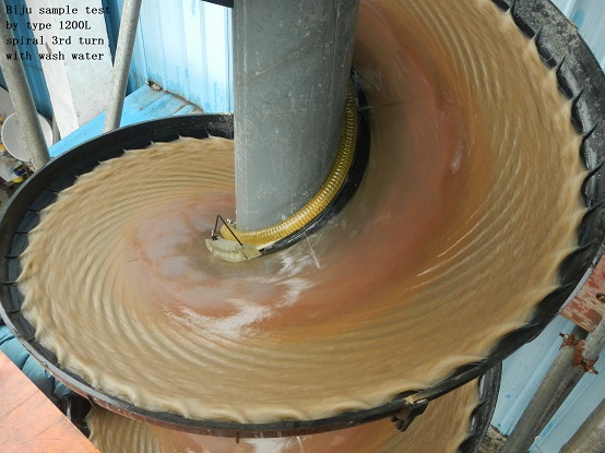
Spiral Concentrators (Flowing Film)
- Separation by density occurs as a result of primary flow and circulating secondary flow patterns that are created as the feed slurry travels along an elongated helical trough surface that spirals downward around a central axis.
- The primary flow is responsible for carrying the particles in the downward direction toward the discharge point.
- The secondary flow caused by retardation of the fluid flow near the trough surface provides the density separation by carrying light particles to the outer trough.
[image 145-4-14]
[145-4-14-c]
Iron Ore Gravity Circuit
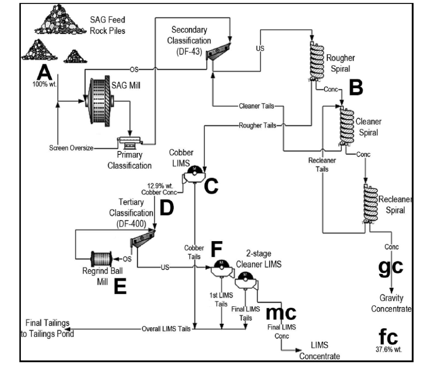
[image 145-4-15]
Chromite Processing
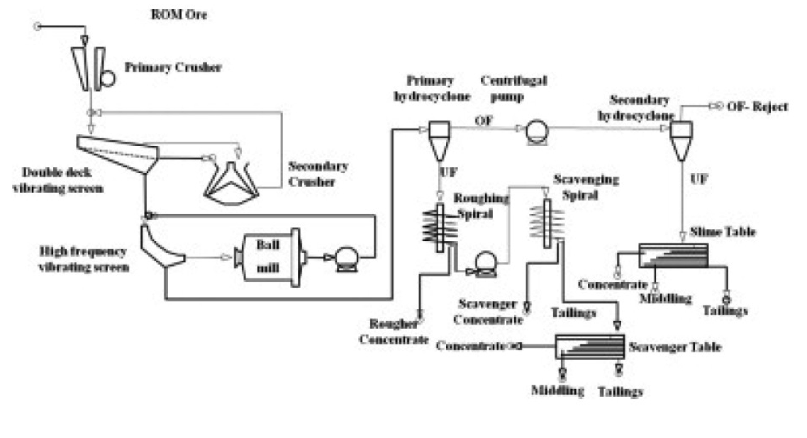
[image 145-4-16]
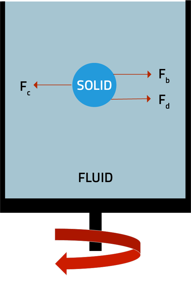
Centrifugal Force, Fc
When the particle size falls below 1 mm, the rate of separation significantly impacts efficiency.
To allow density’based separations, a centrifugal field is applied by either a mechanical action or by accelerating the particles around a rotational axis.
Particle acceleration is given by:
ac = rw2
r = radial distance from center of rotation
ω = angular velocity, (rad/s)
The centrifugal force, Fc , is given by:
Fc= mac= mrw2
The angular velocity ω can be expressed as a function of the tangential velocity of the particle (νT) and the radial distance (r):
w = νr/r
The centrifugal force, Fc is given by:
Fc = mr(νr/r)2 = w = mνT2/r
The angular velocity (ω) is often expressed in terms of the rotational speed, N
w = 2πN/60 where w = 60νr/2πr
The centrifugal force, Fc, is given by:
Fc = mf(2Ï€N/60)2 = 0.01097 mrN2
Centrifugal force is often expressed in the magnitude of the force with respect to the gravitation force (g’s):
Fc/Fg = mrw2/mg = r/g(2Ï€N/60)2 = 0.00118 rN2
Centrifugal Particle Setting Rate
Msap = Fc – Fb – Fd
Fc – centrifugal force
Fb = buoyancy force
Fd = drag force
The terminal settling velocity of a particle in a centrifugal field and under Stokes laminar flow conditions can be expressed as:
νt = rw2d2(Ïs-Ïf)/18μ
[image 145-4-17]
Centrifugal Force Effect
[image 145-4-18]
Enhanced Gravity Separators
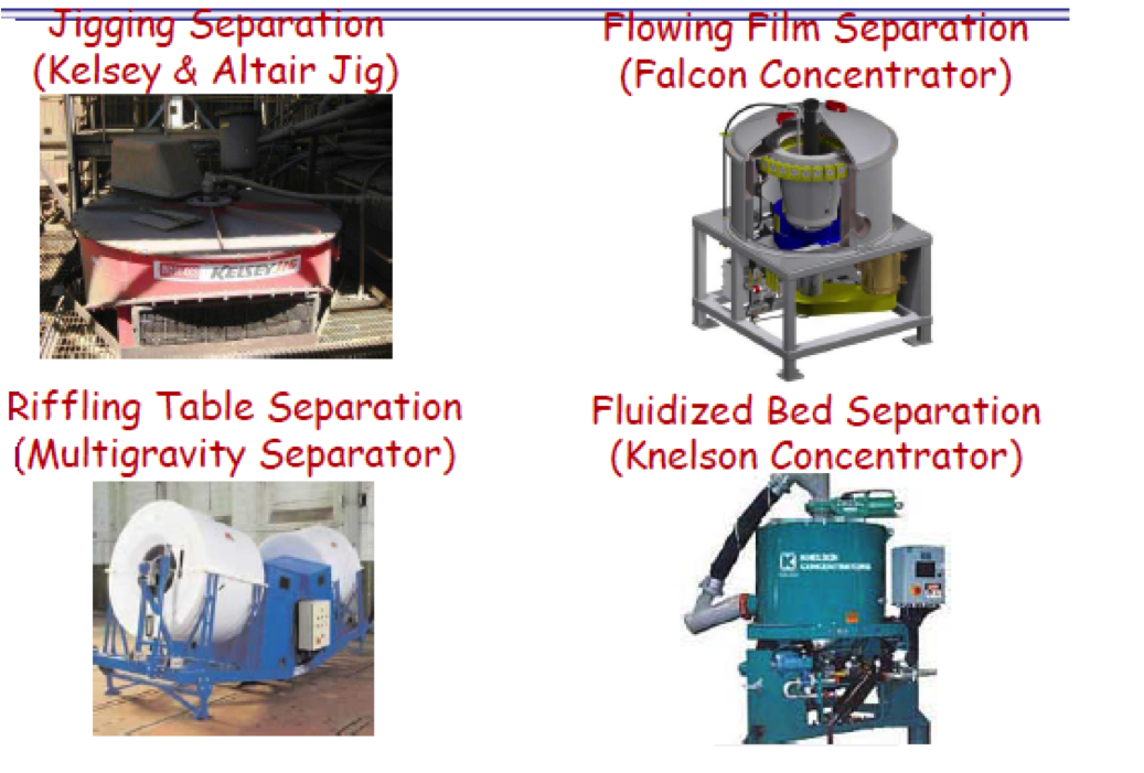
[image 145-4-19]

[image 145-4-20]
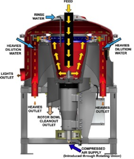
Falcon Concentrator
Flowing film separation principles.
Bed is controlled by the width of the overflow lip.
High density particles removed by a series of valves placed along the circumference of the bow.
Centrifugal forces up to 300 g’s.
Capacities up to 100 tph and around 2200 gpm.
[image 145-4-21]
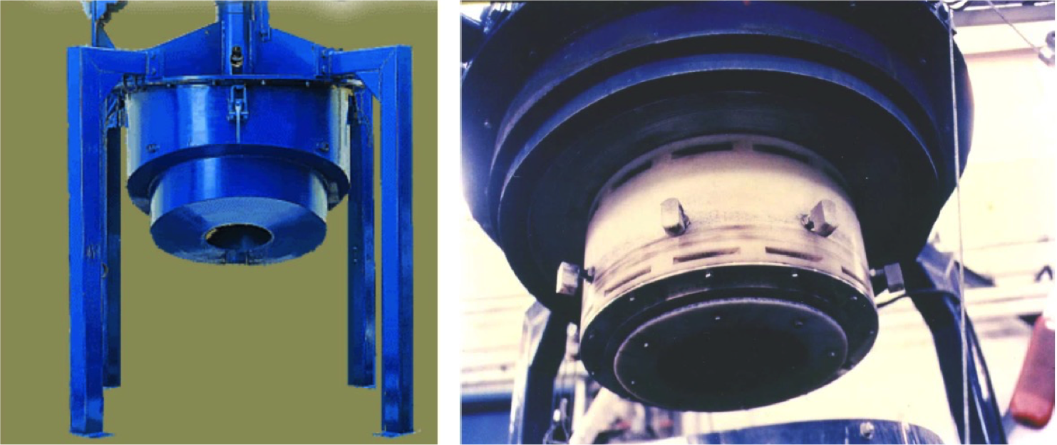
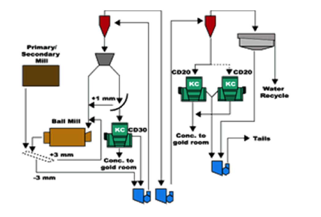
Knelson Concentrator
Fluidized bed separation principles.
Fluidization water is injected through two rings located at the top of a bowl.
High density particles settle against the fluidization water and removed by valves placed along the circumference.
Around 60 G’s of force applied.
Capacities up to 100 tph.

[145-4-22]
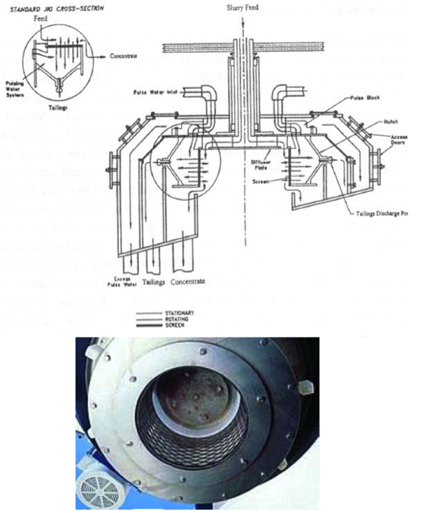
Altair Centrifugal Jig
Rotating bowl contains a cylindrical screen with a lip, whose height can be adjusted to vary the natural depth of the ragging bed.
Pressurized water is injected under the bed periodically through the four pulse-blocks to cause alternating dilation and contraction of the ragging and feed bed
[image 145-4-23]
[image 145-4-24]
Source: Ausenco Services Pty Ltd, Report 2010
Circuit Boards
[image 145-4-26]
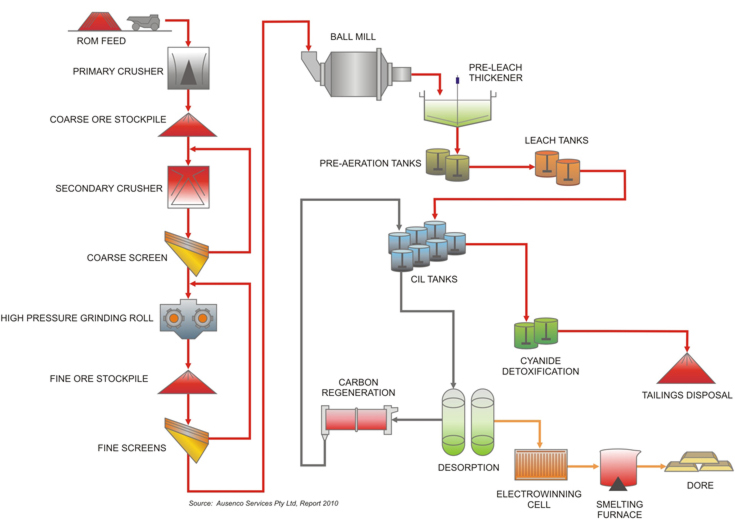
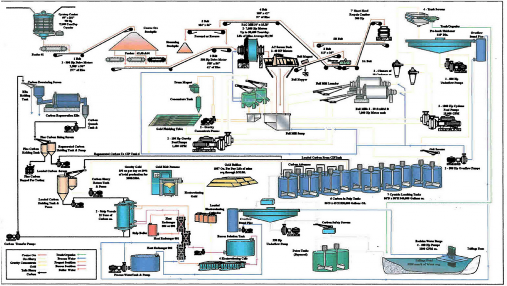
Gold Processing
[145-4-27]
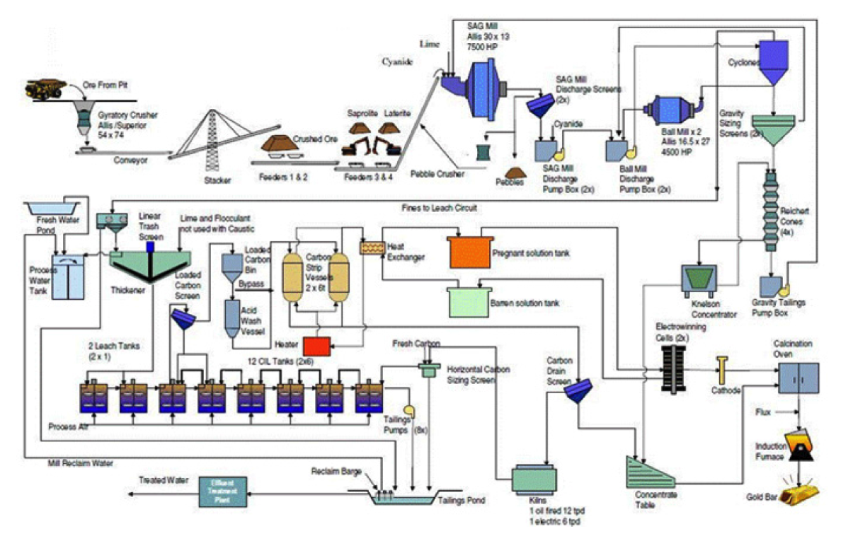
Ft Knox Gold Processing Circuit
[image 145-4-29]