Contents
Objectives
At the end of this less students should be able to:
- Explain the need for crushing operation
- Define terminologies involved in crushing operation
- Explain how crushing works
- Explain the stages involved in crushing operation (Primary, Secondary and Tertiary)
- Recognize different types of crushing equipment used in Mineral industry
- Compare different equipment components and different methods to control the crushing process
Reading & Lecture
The Art of Crushing
Crushing Gravel & Rock
- Limited size reduction
- Cubical shape
- Over and undersize important
- Flexibility
- For gravel: less crushing, more screening
- For rock: crushing and screening
Crushing Ore
- Maximum size reduction
- Shape of no importance
- Over and undersize of minor importance
- Flexibility of minor importance
- More crushing, less screening
- Low production costs, high utilization
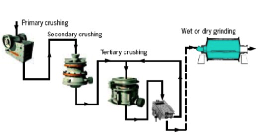
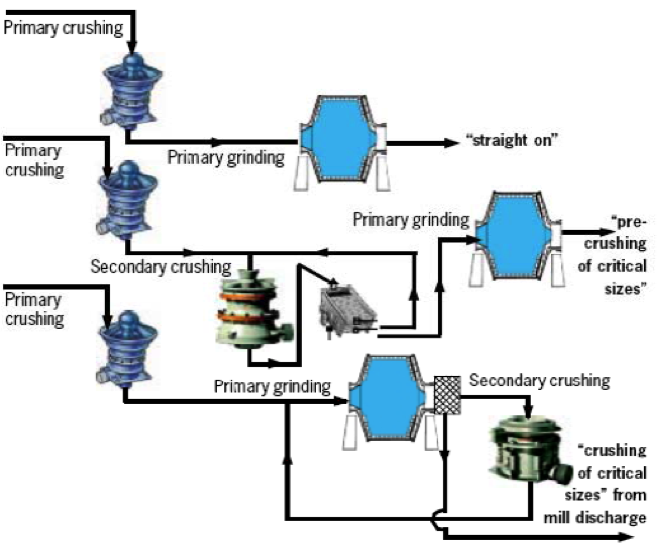
Crushing of Ore and Minerals
- Normally the size reduction by crushing is of limited importance besides the top size of the product going to grinding.
- This means that the number of crushing stages can be reduced depending on the feed size accepted by primary grinding stage.
Calculation of Reduction Ratio in Crushing
Crushing Equipment
- The selection of the right crushing equipment is influenced by many factors some of which are upstream of the crushing plant (e.g. blasting pattern and mining method) and others which are downstream of the crushing plant (e.g. mill and grinding circuit selection).
- Crushers have more efficient transfer of applied power to the breakage of rock than grinding mills.
- Typically a crushing flowsheet for a mineral processing plant will have from one-to-three stages of crushing. There are some cases where the process requires a fine dry product and a quaternary stage of crushing will also be included.
Primary Crushing
- The purpose of the primary crusher is to reduce the ROM ore to a size amenable for feeding the secondary crusher or the SAG mill grinding circuit.
- The ratio of reduction through a primary crusher can be up to about 8:1.
- Feed:
- ROM up to 1.5 m
- Product:
- -300mm (for transport) to -200mm (for SAG mill)
- Feed Rate:
- 160 to 13,000 tph
- The family of primary crushers include:
- Gyratory Crushers
- Jaw Crushers
- Impact Crushers
- Typical rules for primary crusher selection:
- Rule 1: Always use a jaw crusher if you can due to lower costs.
- Rule 2: For low capacity applications, use jaw crusher and hydraulic hammer for oversize.
- Rule 3: For high capacities, use jaw crusher with big intake openings.
- Rule 4: For very high capacities, use gyratory crusher.
Jaw Crusher
- Crushing occurs between two moving plates that are arranged to form an acute angle to apply a compressive force that results in tensile failure
- Typically preferred for feed rates of 900 tph or less.
- Can be located underground or surface
- Typically only a primary crusher.
- Operated in open circuit
- The gape and the width are set values for a given crusher while the setting can be altered to adjust the product size.
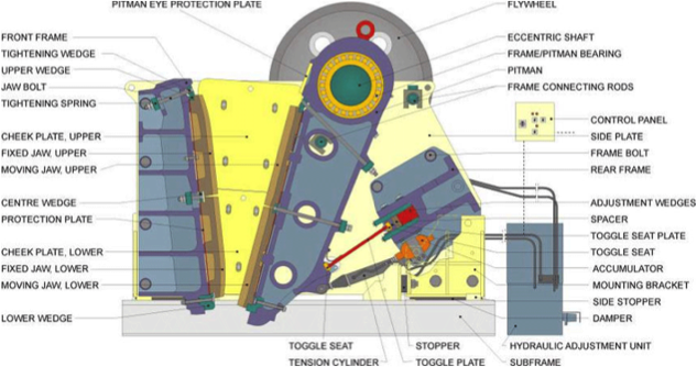
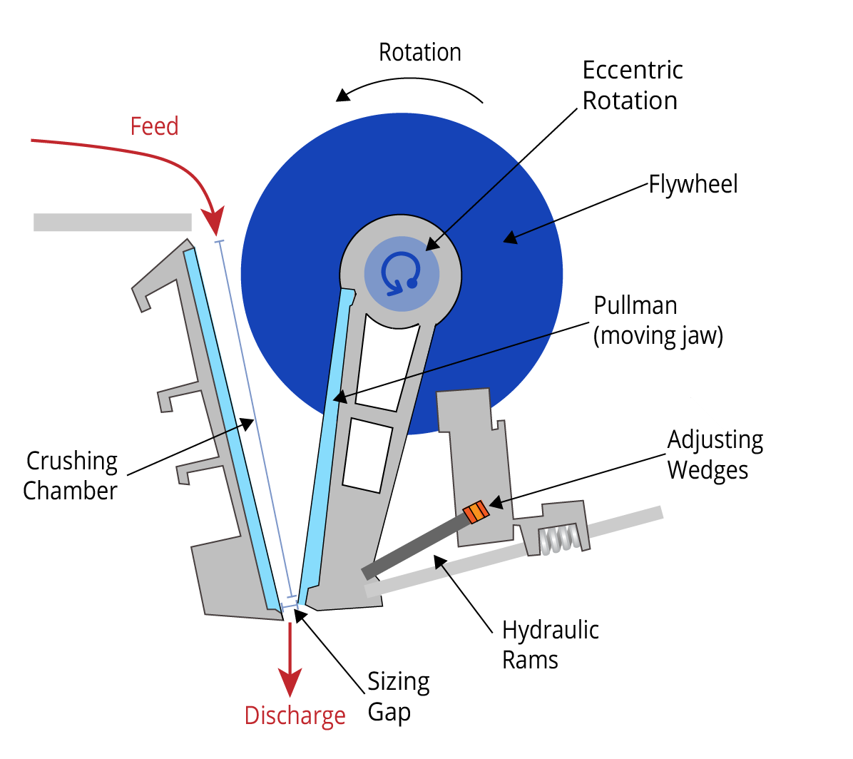
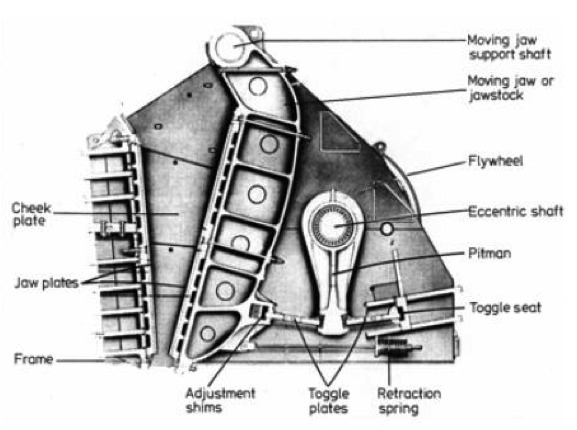
Single Toggle Jaw Crusher
- The maximum motion is at the top of the jaw.
- Light to medium duty crusher and capable of crushing ores up to 200 Mpa (27.500 psi)
Double Toggle Jaw Crusher
- The maximum motion is at the bottom of the jaw
- Capable of crushing ores up to 350 Mpa (90,000 psi)
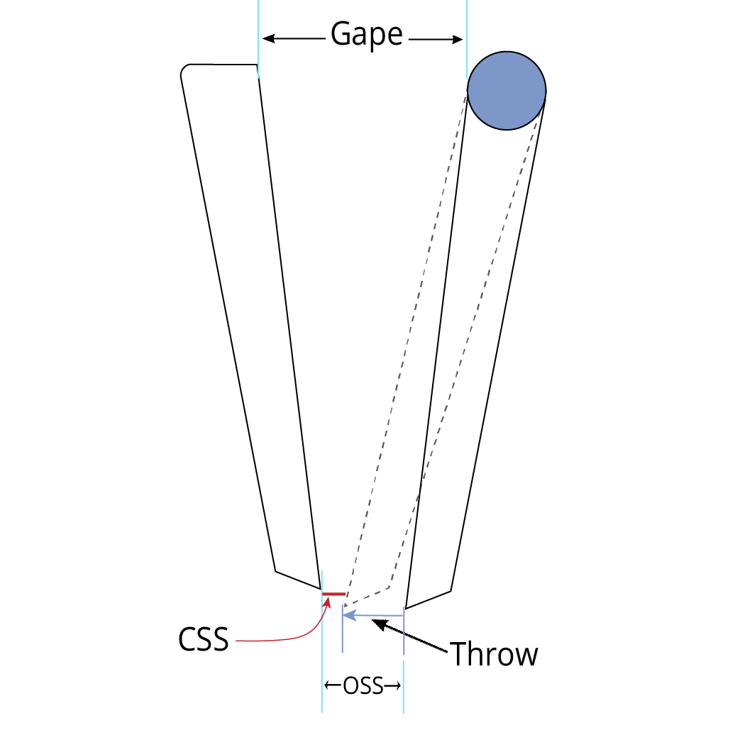
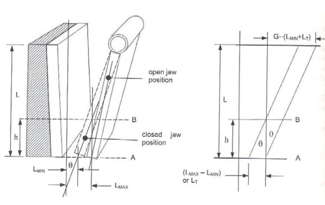
The dimensions defined by those particle sizes are:
- Gape: The distance between the jaws at the feed opening
- Closed side set (CSS): The minimum opening between the jaws during the crushing cycle (minimum discharge aperture)
- Open side set (OSS): The maximum discharge aperture
- Throw: The stroke of the swing jaw and the difference between OSS and CSS.
[image: (135-5-9)]
Jaw Crusher Fundamentals
- Vertical Height = 2 x Gape
- Width of Jaw > 1.3 x Gape
< 3.0 x Gape
- Throw = 0.0502 (Gape) 0.85
- Gape is measured in meters.
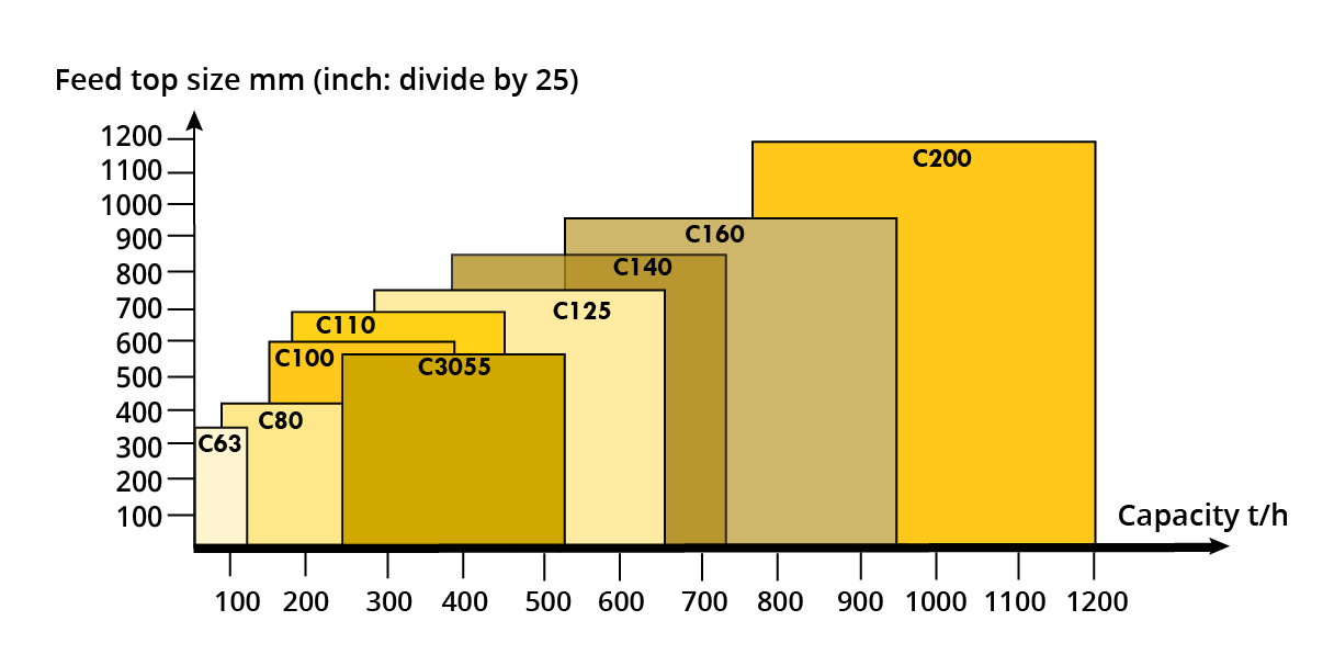
Jaw Crusher Sizes and Power Ratings
- Size is specified in terms of the gape and width, typically listed as gape x width.
- Largest jaw crusher is 1600 x 2514 mm with motor ratings of 250-300 kW.
- Metso crushers (C200 series) are 1600 x 2514 mm with motors rated at 400 kW.
- The largest particle that can enter the opening of the jaw crusher can be estimated by:
Largest particle size= 0.9 x gape
- The largest particle to report to the jaw crusher is typically defined by the drilling pattern in the mine.
Typical Jaw Crusher Characteristics
| Jaw Crusher | Size (mm) | Reduction Rate Range | Power (kW) | ||||
| Gape | Width | Min | Max | ||||
| Min | Max | Min | Max | ||||
| Double Toggle | 125 | 1600 | 150 | 2100 | 4:1-9:1 | 2.5 | 225 |
| Single Toggle | 125 | 1600 | 150 | 2100 | 4:1-9:1 | 2.5 | 400 |
Toggle Speed:
- maximum = 300 rpm
- minimum = 100 rpm
Jaw Crushers (Metso Minerals)
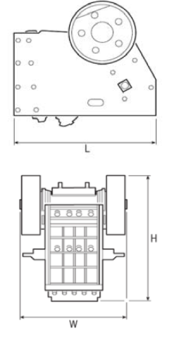
Jaw Crusher Specifications
| Type | H mm (inch) | L mm (inch) | W mm (inch) | Weight (ton) | KW/hp Max Power |
|---|---|---|---|---|---|
| C63 | 1600 (63) | 1950 (77) | 1390 (55) | 6.05 | 45/60 |
| C80 | 1700 (67) | 2020 (80) | 1565 (62) | 7.52 | 75/100 |
| C100 | 2400 (95) | 2880 (113) | 2250 (89) | 20.10 | 110/150 |
| C105 | 2050 (81) | 2630 (104) | 1920 (76) | 13.50 | 110/150 |
| C110 | 2670 (105) | 2830 (112) | 2385 (94) | 25.06 | 160/200 |
| C125 | 2900 (114) | 3370 (133) | 2690 (106) | 36.70 | 160/200 |
| C140 | 3060 (121) | 3645 (144) | 2890 (114) | 45.30 | 200/250 |
| C145 | 3330 (131) | 3855 (152) | 2870 (113) | 53.80 | 200/250 |
| C160 | 3500 (140) | 4200 (165) | 3180 (125) | 68.60 | 250/300 |
| C200 | 4220 (166) | 4870 (192) | 3890 (153) | 118.40 | 400/500 |
| C3055 | 2400 (95) | 2920 (115) | 2550 (100) | 25.50 | 160/200 |
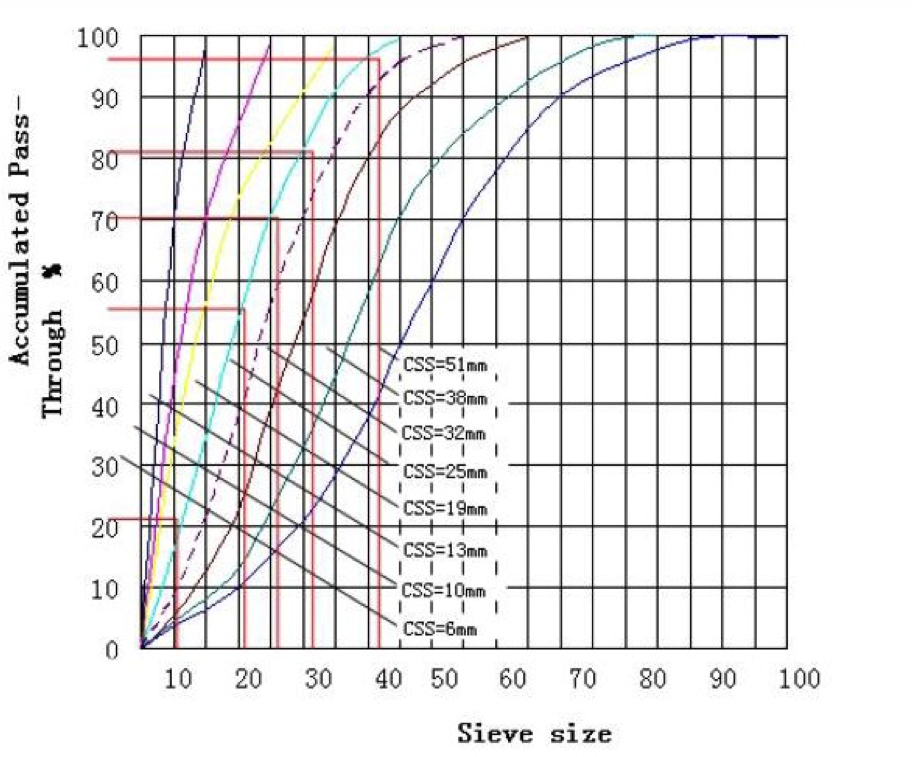
Closed-Side Setting Effect on Feed Size
Measurement of the crusher’s closed side setting (CSS) varies depending on the jaw profile that is being used and has an impact on the crusher’s capacity and product gradation.
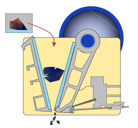
Feeding Jaw Crushers
- It is desirable to feed jaw crushers continuously.
- However, feed is often provided intermittently using front end loaders, shovels or trucks.
- When the feed rate exceeds the product rate, the condition is known as choke feeding.
- In choke feeding, particle breakage occurs between the plates and particles and between the particles themselves.
- Choke feeding produces fines; desirable for liberation purposes.
Typical Jaw Crusher Operation
- Product size is smaller than the open side setting.
- Typical operating and performance characteristics:
| Top Feed Size | = 0.8- 0.9 x Gape |
| Reduction Ratio | = 4:1 to 7:1 |
| Throw | = 1 – 7em |
| Speed | = 100 – 359 rpm |
| Frequency of Stroke | = 100 – 300 cycles/minute |
Jaw Crusher Capacity
- Capacity is primarily a function of:
- crusher design characteristics such as width and depth of crushing chamber.
- open and closed side settings.
- options on feeding method, intermittent or continuous.
- operating characteristics like the length of stroke, the number of strokes per minute, and the nip angle.
- Mathematically, capacity can be represented by the expression:
| w = width | Lr – length of stroke |
| L = height | n = frequency (rpm) |
| Lmax = open side setting | K = machine characteristic constant |
| Lmin = closed side setting | θ – jaw angle |
Critical Jaw Crusher Parameters
Frequency Effect on Capacity
- Rose and Hill (1967) considered crusher capacity by determining the amount of time and distance a particle takes between two jaw plates.
- Particles in the A-B zone discharges at the next reverse movement of the jaw.
- The maximum size of a particle dropping out of the crusher dmax is determined by the open size setting (Lmax).
- The rate at which the crushed particles move through the crusher is a function of the cycle frequency, Ï….
- Rose and Hill (1967) recognized that the capacity of a jaw crusher increases with frequency up to a maximum and then decreases with a further increase in frequency.
- Above a critical frequency Ï…c, the particles are unable to move downward a distance h during each cycle.
- Rose and Hill derived an expression for quantifying the critical frequency value.
- At this frequency, the maximum capacity is realized.
Jaw Crusher Advantages
- Lower installed cost than gyratory crushers.
- Can handle high abrasion with low maintenance.
Jaw Crusher Disadvantages
- Maximum capacity of 1,000 MTPH.
- Can be used for primary crushing only.
Gyratory Crushers
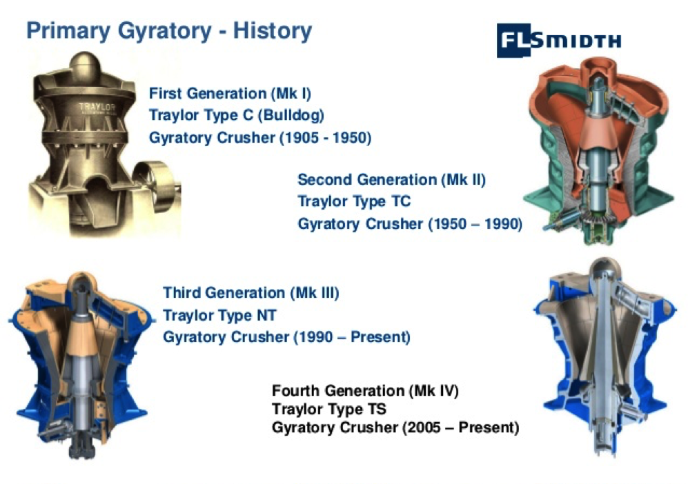
- Invented by Charles Brown in 1877 and developed by Gates in 1881; Gates Crusher.
- A conical element is supported in a flared shell or frame creating a chamber wide at the top and narrow at the bottom.
- The center element is caused to gyrate about its fulcrum point causing it to advance and retreat with relation to the shell.
- Rock introduced at the top is broken as it passes through the crusher chamber.
- Typical Capacities:
- Reduction Ratio = 3:1 to 10:1
- 300 to 9100 tph
https://youtu.be/1CpjRMICXNM
Gyratory Crusher History
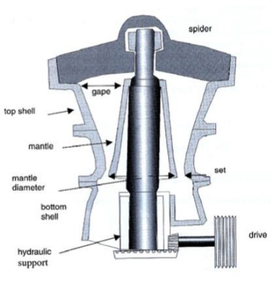
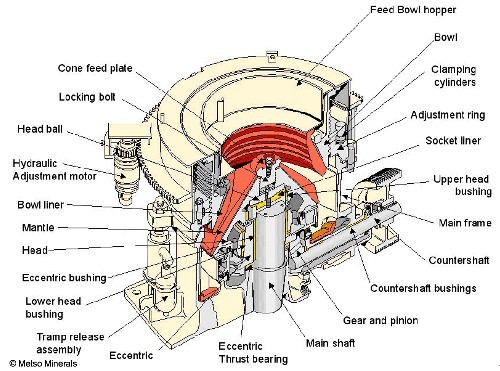
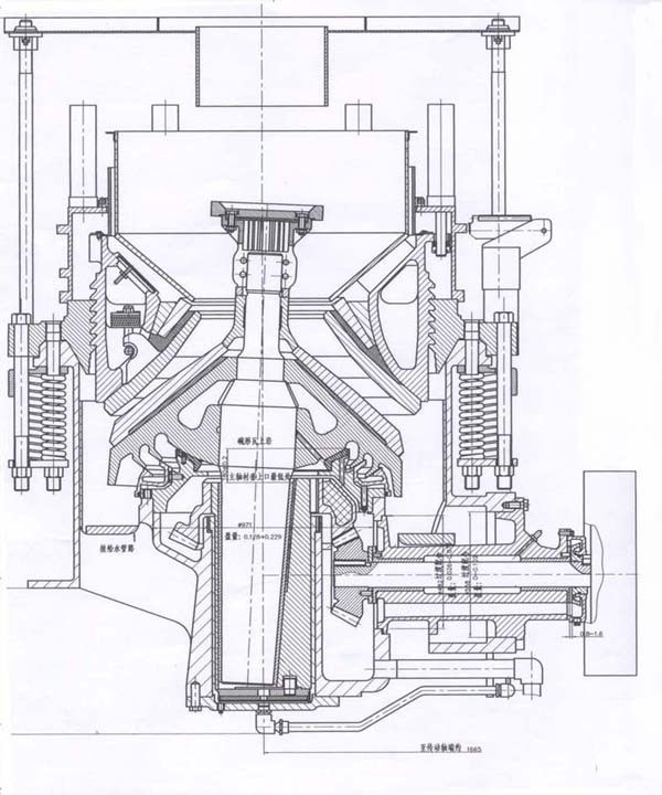
Gyratory Crusher Dimensions
- Breaking head (mantle) is fixed to a central spindle which is suspended from a spider hydraulically or mechanically.
- Bottom end of the spindle is connect to a bevel and pinion arrangement.
- Primarily compressive breakage.
- Tolerates different particle shapes including slabby rock.
- Dimensions :
- For sizes < 66cm, the circumference along the opening = 8-10 x Gape
- For sizes > 66cm, the circumference = 6.5 x 7.5 x Gape.
- Mantle diameter to Gape = 1.3-1.7:10.
- Feed size= 0.9 x Gape
- Angle of nip varies for large crusher between 21 °to 24 °. For curved surfaces, the nip varies from 27 ° to 30 °.
- The distances between the concave surface and the mantle on top and bottom are usually used to describe the size of the crusher.
- Other characteristic identifications:
- Bowl diameter at the discharge x Gape
- Bowl diameter at the feed end x Gape
- Bowl circumference at the feed end x Gape
- Maximum diameter at the head x Gape.
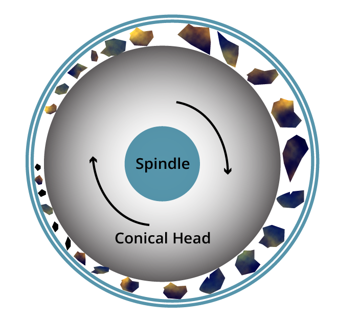
Gyratory Crushing Action
- Designs of the breaking faces vary with manufacturer.
- As a result, the product size distribution varies.
- When the feed drops into the crusher, the mantle squeezes the rock against the concave surface.
- When the mantle moves away and the rock drops down further and subject to additional crushing during the next cycle .
- Material exits the crusher through the open side setting.
- Thus, the top size of the product is determined by the open side setting.
Long Shaft Gyratory (generally, not used commercially)
| Characteristics | Small | Large |
|---|---|---|
| Size, mm | 63 - 711 | 1829 - 2294 |
| Set Range | 25.4 - 44.5 | 228 - 305 |
| Rev/minute | 700 | 175 |
| Power, kW | 2.2 | 298 |
Short Shaft Gyratory
| Characteristics | Small | Large |
|---|---|---|
| Size, mm | 762 - 1524 | 2133 - 2794 |
| Set Range | 50.8 - 152 | 178 - 305 |
| Rev/Minute | 425 | 275 |
| Power, kW | 149 | 750 |
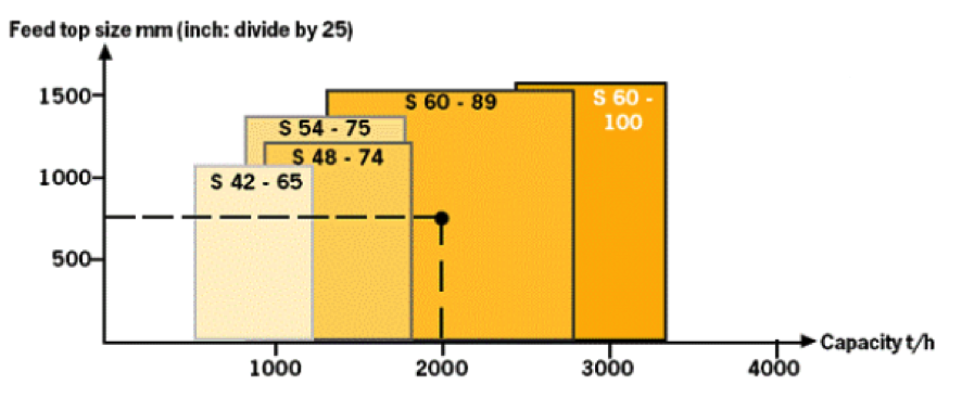
Gyratory Design Characteristics
| Type | H mm (inch) | W mm (inch) | Weight (ton) Max Power | kW/hp |
|---|---|---|---|---|
| S 42-65 | 4807 (189) | 3937 (155) | 119.4 | 375/502 |
| S 48-74 | 5915 (233) | 4597 (181) | 248.0 | 450/603 |
| S 54-75 | 5915 (233) | 4928 (194) | 248.0 | 450/603 |
| S 60-89 | 7169 (282) | 6299 (248) | 570.0 | 750/1006 |
[image: (135-5-18)]
Gyratory Circuit Design
- Large units are rarely installed underground.
- Charge is fed by trucks, tip-wagons, side dump cars, and conveyor belts.
- Feed enters from a hopper and passes through a grizzly screen to remove oversize
- Gyratory crushers are operated in open circuit.
- The feed is limited to 1 to 1.5 meters in size.
- Thus, based on reduction ratio, the rock size is reduced to 10 to 15 cm.
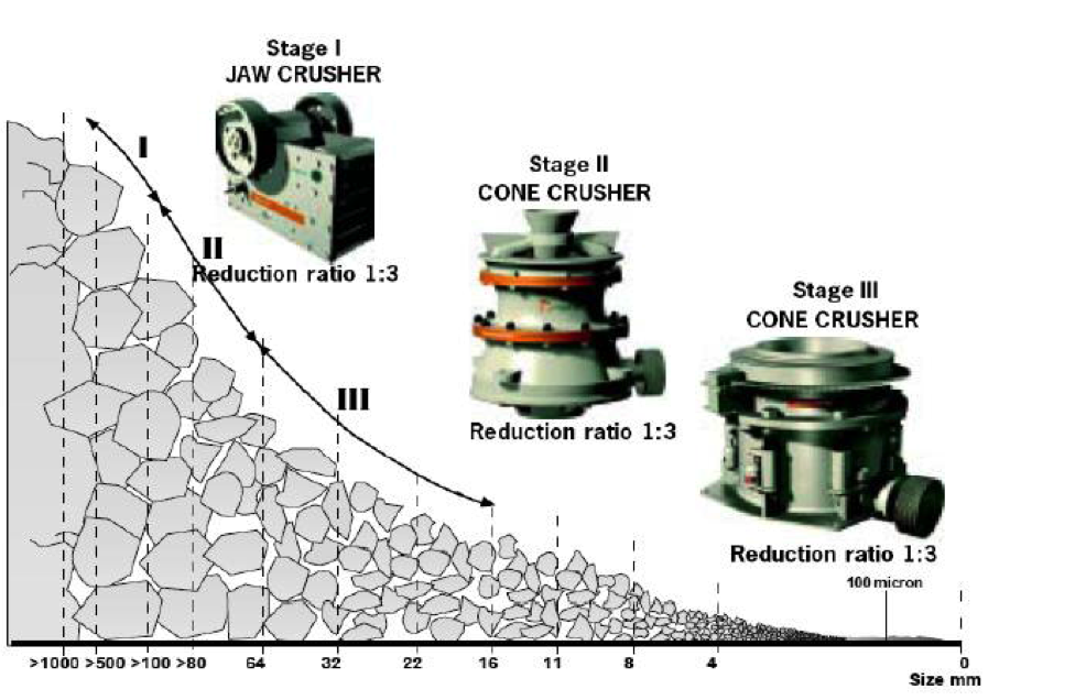
- Typical reduction ratios are:
- Primary crusher: 3:1 to 10:1
- Secondary crusher: 6:1 to 8:1
- Tertiary crusher: 10:1
Therefore, if a 3 mm crusher product is required, maximum feed size to the secondary crusher would be 240 mm. Thus, the feed to the primary crusher should not exceed 2400 mm.
Gyratory Operation
- Performed in dry conditions.
- Water may be used occasionally for lubrication purposes .
- Up to 8%-10% moisture feed is acceptable; however, fines should be less than 10%.
- Performance affected by:
- Feed fines content (< 10%)
- Inherent and total moisture content
- Feed distribution in the crushing area
- Feed bulk density
- Hardness of ore (W;)
- Recirculating load
| Size (Gape x Mantle Dia., mm) | LMAX (open side, mm) | LMIN (closed side, mm) | Gyration/min | Capacity (t/h) | Work Index (kWh/t) |
|---|---|---|---|---|---|
| 1219 x 1879 | 200 | 34 | 135 | 2200 | -- |
| 1371 x 1879 | 137-223 | 44 | 135 | 3100 | -- |
| 1828 x 2311 | 194 | 44 | 111 | 2750 | 13 |
| 1524 x 2268 | 200 - 275 | 37 | 113 | 3200 | 6 |
| 1524 x 2268 | 238-275 | 37 | 92 | 3180 | 12 |
| 1219 x 2057 | 175-188 | 37 | 93 | 1330 | 10 |
| 1524 x | 225 | 34 | 134 | 2290 | -- |
Minimum Gyration Speed
- The gyration speed determines that rate at which product is generated at the desired particle size .
- It is also known that gyration speed must be slowed if the particle size of the feed is increased.
- Friction controls the flowability of the material through the gyratory.
- Friction values are typically between 0.2 and 0.3 .
- For a cone angle of 75 °, friction of 0.2, and product size of 10.2 cm, the minimum gyration speed is 190 rpm.
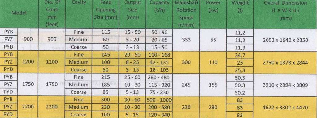
| Model | Gape (mm) | LMAX (mm) | Capacity (tph) |
|---|---|---|---|
| 42-65 | 1065 | 140-175 | 1635-2320 |
| 50-65 | 1270 | 150-175 | 2245-2760 |
| 54-75 | 1370 | 150-200 | 2555-3385 |
| 62-75 | 1575 | 150-200 | 2575-3720 |
| 60-89 | 1525 | 1645-230 | 4100-5550 |
| 60-110 | 1525 | 175-250 | 5575 - 7605 |
Specific Power Requirements
- Run-of-mine material contains a range of particle sizes
- Thus, only the power required to break particles that are greater than the open-side setting should be included in the overall power requirement
- In actual practice, it has been found that the total power requirement PA is:
P ↓A = 0.75 Q P - This expression is valid for primary crushers. For secondary cone crushers, the 0.75 value takes a value of unity.
Advantages vs. Disadvantages of Gyratory Crushers
Advantages:
- Designed for direct dump from trucks up to 300 tons.
- High capacity rating.
- Lowest maintenance per ton processed .
- Highest availability.
- Can handle crushing ore with compressive strength of up to 600 MPa (90,000psi).
Disadvantages:
- Highest installed capital cost.
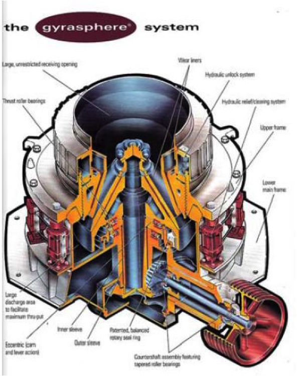
Cone Crushers
- Originally designed and developed by Symons (1920).
- Similar to gyratory except the spindle is supported at the bottom of the gyrating cone instead of being suspended.
- The head to depth ratio is larger than gyratory crushers.
- Cone angle are flatter and the slope of the mantle and concaves are parallel.
- The flatter cone angles increase residence time and thus produce finer particles.
- Shell is held by springs which allow passage of unbreakable rock.
- Breakage is by impact.
- Secondary crushers are typically Standard Head with stepped liners
- Tertiary crushers are Short head which have smoother crushing faces and steeper breaking head cone angles.
Standard Symons Cone Crushers
| Design Characteristics | Open Circuit | Closed Circuit | ||
|---|---|---|---|---|
| Maximum | Minimum | Maximum | Minimum | |
| Size (mm) | 3050 | 600 | 3050 | 600 |
| Crusher Chamber Size (mm) | 76-432 | 25-76 | 76-178 | 25-51 |
| Discharge Setting (mm) | 22-38.1 | 6.4-15.8 | 6.4-15-19 | 3.2 |
| Power (kW) | 300-500 | 25-30 | 300-500 | 25-30 |
Typical Metso Cone Crusher Capacities
| Crusher | Type | Feed Opening (mm) | Lmin (mm) | Capacity (tph) |
|---|---|---|---|---|
| HP800 Standard Head | Fine | 267 | 25 | 495-730 |
| Medium | 297 | 32 | 545-800 | |
| Coarse | 353 | 32 | 545-800 | |
| HP800 Short Head | Fine | 33 | 5 | --- |
| Medium | 92 | 10 | 260-335 | |
| Coarse | 155 | 13 | 325-425 | |
| MP1000 Standard 2392 mm | Fine | 300 | 25 | 915-1210 |
| Medium | 390 | 32 | --- | |
| Coarse | 414 | 38 | 1375-1750 |
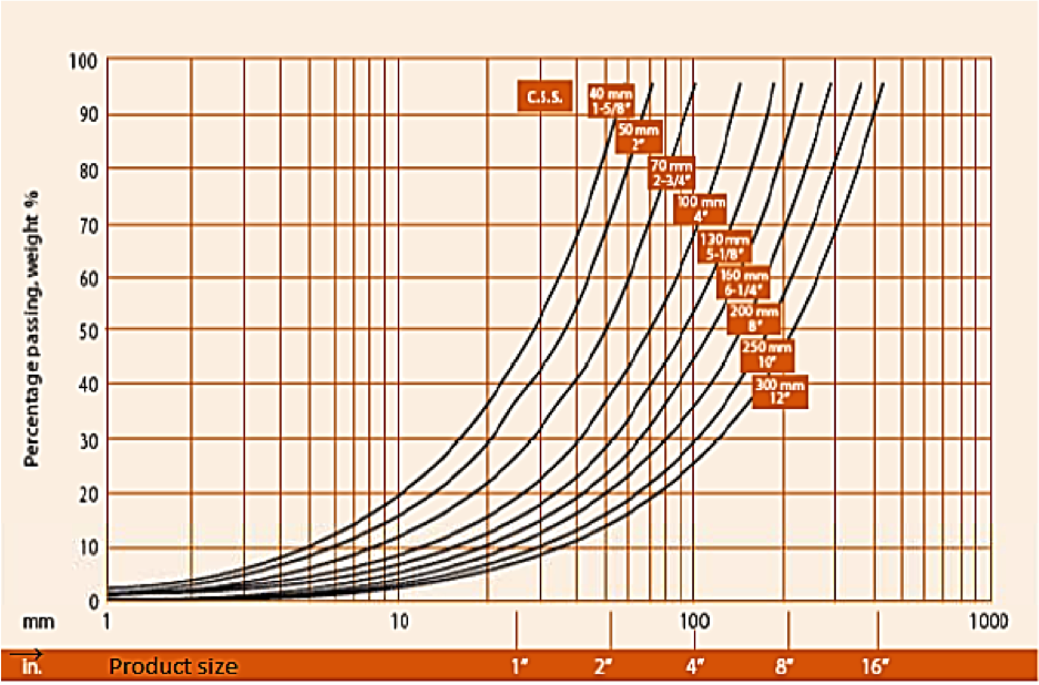
Commercial Cone Crushers
Cone Crushers Product Distributions
Gyradisk Cone Crusher
- For finer size products (e.g., -6 mm), a special cone crusher known as the Gyradisc is commonly used.
- Operation is similar to the Standard Cone Head; however, breakage is mostly by attrition rather than impact.
- Reduction ratio is around 8:1.
- Feed size is limited to less than 50 mm with a nip angle between 25 ° and 30 °.
- Head diameters are between 900 and 2100 mm.
- The Gyradisc is normally maintained in choke feed mode.
- Product size between 6 and 9 mm.
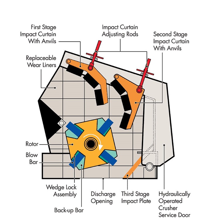
Impact Crushers
- One or two heavy rotors carrying fastened projections, revolve inside a cas1ng.
- The projections break the rock by primary impact and propels the rock against the case for the secondary impact.
- Impactors are utilized in soft and non- abrasive applications.
Advantages:
- Can handle a large size reduction: 1 m to 75mm
- High reduction ration for amount of investment.
- Impactor provides a high degree of fines (for ores).
- Can handle up to 2500 MTPH.
Disadvantages:
- Power consumption is higher as more fines are produced.
- Cannot handle tramp metal.
- Requires feeder.
Save