Contents
Objectives
At the end of this lesson students should be able to:
- Explain the role of ball mill in mineral industry and why it is extensively used.
- Describe different types of ball mill design.
- Describe the components of ball mill.
- Explain their understanding of ball mill operation.
- Explain the role of critical speed and power draw in design and process control.
- Recognize important considerations in ball mill selection.
Reading & Lecture
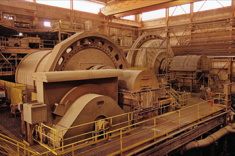
- In ball mills, steel balls or hard pebbles to break particle based on impact and attrition.
- A rotating mill charged with media and ore is lifted against the inside perimeter.
- Some of the media falls and impacts the ore particles at the bottom of the mill.
- The rest of the media cascades and, in the process, creates particle breakage by attrition.
- The process is continuously repeated as the particles move by mass and volume action through the mill.
- Dry and wet grinding common.
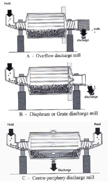
Mill Type Overview
- Three types of mill design are common.
- The Overflow Discharge mill is best suited for fine grinding to 75 – 106 microns.
- The Diaphram or Grate Discharge mill keeps coarse particles within the mill for additional grinding and typically used for grinds to 150 – 250 microns.
- The Center-Periphery Discharge mill has feed reporting from both ends and the product discharges from the center bottom.
- In all systems, the feed trunnion is smaller than the discharge trunnion to ensure a good flow and no backflow to the feed.
Ball Mill Design Parameters
Size rated as diameter x length.
Feed System
- One hopper feed
- Diameter 40 – 100 cm at 30 ° to 60 °
- Top of feed hopper at least 1.5 meter above the center line of the mill.
Feeder
- Single or double helical scoop feeder or a spout feeder
- Double helical feeders used in closed-circuit with classifiers
- Spout feeders preferred when using a closed-circuit with classifying cyclones. Cyclones are typically installed above the mill and thus the cyclone underflow is fed to the mill by gravity.
Discharge System
- One exit unit
- Exit about 5 – 110 cm lower than the center line of the overflow mill.
Comparison of Tumbling Mill Characteristics
| Parameter | Ball Mill | Rod Mill | Autogenous Mill |
|---|---|---|---|
| Length: Diameter Ratio | 1.4 to 1.8 | 0.5 to 3.5 | 0.25 to 0.50 |
| Feed Size | 2.5 cm maximum | -1.9 cm -1.25 to 0.9cm | Coarse Ore Normal Ore |
| Reduction Ratio | 15:1 to 20:1 | 20:1 to 200:1 | --- |
Ball Mill Design
- A survey of Australian processing plants revealed a maximum ball mill diameter of 5.24 meters and length of 8.84 meters (Morrell, 1996).
- Autogenous mills range up to 12 meters in diameter.
- The length-to-diameter ratios in the previous table are for normal applications.
- For primary grinding, the ratio could vary between 1:1and 1.8:1.
- For fine regrinding in open circuit, the ratio ranges from 1.3:1 to 1.5:1.
- Some ball mills are separated in to compartments by grates. The grates hold back particles above a certain size for additional grinding.
- The compartments could contain different ball sizes. Large to small from the feed end.
- Some mills have a conical section. In the conical section near the discharge, fine particles preferentially move into the conical section thereby creating segregation. This type has low feed capacity and is rarely used in the metallurgical industry.
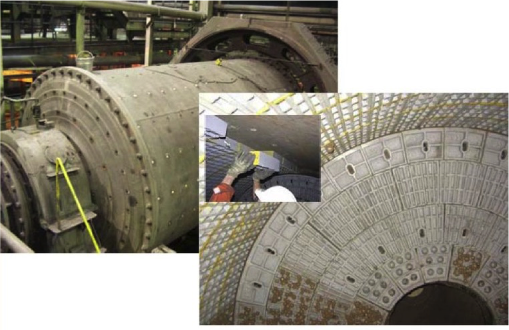
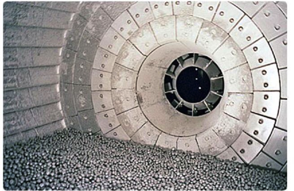
Lifters and Media
Lifters are used on the inside [Periphery of the mill to:
- Save wear on the steel body;
- Assist the lift of the media and ore to the desired height in the mill.
Liners can be made of manganese steel, Ni hard or high carbon steel and hard rubber or synthetic material that is 65 – 75 mm thick.
The liners can be:
- Smooth
- Ribbed
- Waved
- Double wave liners: 65 — 90 mm above liner thickness
- Single Wave Liners: 60- 75mm above liner thickness
Liner wear is roughly proportional to rotation speed.
Mill Liners
![Mill liners [images: (135-7-4)]](https://millops.community.uaf.edu/wp-content/uploads/sites/605/2016/04/fig4.png)
Mill Lifters
The number of lifters generally can be determined by the rule-of-thumb:
Number of Lifters = 3nD for double wave liners
= 6.6D for single wave liners where D is the mill diameter (m).
Double wave liners are more suitable for ball sizes less than 60 mm. Otherwise, single wave is preferred.
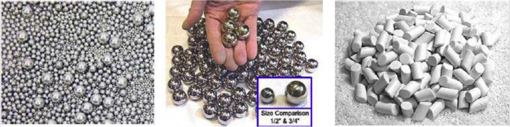
Grinding Media
- The bulk densities of the steel media typically used are:
Balls 4650 kg/m3 Cylpebs 4700 kg/m3
Rods 6247 kg/m3 Cubes 5500 kg/m3 - For soft ore, ceramic media (90 °/o A l203) can be used (2200 kg/m3).
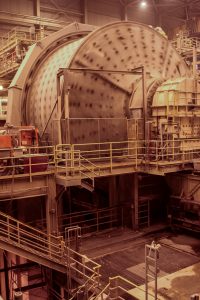
Ball Mill Operation
- Ball mills ride on steel tires or supported on both ends by trunnions.
- Girth gears bolted to the shell drive the mill through a pinion shaft from a prime mover drive.
- The prime movers are usually synchronized motors.
- During rotation, a portion of the charge is lifted along the inside perimeter.
- After exceeding the angle of repose, part of the charge slides down while part cascades.

Mill Breakage Mechanism
- According to Morrell (1996), the breakage mechanism is association with media characteristics:
- Impact Breakage ∞ M↓B↑3 MB = ball mass
- Attrition Breakage ∞ S↓B↑3 SB = ball surface area
- The energy of impact will depend on height and the angle of impact.
- The size reduction will depend on:
- Charge characteristics (mass, volume, hardness, density, size distribution);
- Grinding media characteristics (mass, density, number, ball size distribution);
- Speed of mill rotation;
- Slurry density when wet grinding
Charge Volume
- Mill should not be overcharged or undercharged
- Overloading tends to accumulate fines at the toe of the mill which results in a cushioning effect.
- When the rock load is low, excessive ball-to-ball contact retards the rate of breakage.
- The fraction of mill volume occupied by the ore, J↓R:
J↓R=M↓R / Ï↓S / V↓M x1 / 1—φ MR = rock mass
φ = porosity of charge bed - The percent of mill volume occupied by grinding media, J↓B:
J↓R = M↓R / Ï↓S / V↓M x1 / 1—φ MB – ball media mass
φB = density of ball media
Charge Height
- Measurement of charge height is a convenient method to estimate charge volume.
- Generally :
- For overflow ball mills, the charge should not exceed 45% of the mill volume .
- For grate discharge mills, the charge should occupy about 50% of the mill volume .
- Bond developed a relationship that can be used to determine the percent charge by volume as a function of the vertical height above the charge, He, and the radius of the mill, R, i.e.,
Charge% = 113-(63HC/R) - However, Morrell identified significant errors from this estimate when using small media sizes.
Medium Charge Volume Fraction
- The fraction of the mill volume occupied by the mill charge can be estimated based on a ratio of the cross-sectional areas.
- The cross-sectional area of the mill charge (AC) can be determined from:
A↓C = H↓B / 6W (3H↓B↑2 + 4W↑2) - Since the cross-sectional area of the mill is simply πR2, the mill volume fraction occupied by the media charge is:
J↓B = A↓C / Ï€R↑2 – H↓B / 6W (3H↓B↑2 + 4W↑2) (1/Ï€R↑2)
where W = 2(R↑2 – H↑2) ↑ 0.5
Ball Size as Initial Charge
- Commercial ball sizes 10 – 150 mm
- Number, size and mass of each ball size depends on mill load and whether or not the media is being added as the initial charge.
- For the initial chargin of a mill, Coghill and DeVaney (1937) defined the ball size as a function of the top size of the feed, i.e.,
d↓V = 0.40 K√F
dB = ball size (cm)
F = feed size (cm)
K = proportionality constant described as the grindability factor- Hard ores, K = 37.4;
- Soft ores, K = 29.8
Ball Size vs. Grindability
It has been recognized that the grindability of an ore in a ball mill is a function of both feed and mill parameters:
- Work index, Wi
- Largest particle size and size distribution
- Density of solids and slurry
- Mill diameter
- Rotational speed
Rowland and Kjos (1980) defined the largest ball size needed based on these parameters:
d↓B = 25.4 [(F↓80 / k) ↑0.5 (Ï↓s W↓i / 100φ↓C (3.281 D) ↑0.5) ↑0.33 ] mm
Where:
D = inside diameter of mill (meters)
φC = fraction of the mill critical speed
k = mill factor constant
Mill Factor, k
| Mill Type | Wet/Dry Grinding | Circuit | k value |
|---|---|---|---|
| Overflow | Wet | Open | 350 |
| Overflow | Wet | Close | 350 |
| Diaphragm | Wet | Open | 330 |
| Diaphragm | Wet | Close | 330 |
| Diaphragm | Dry | Open | 335 |
| Diaphragm | Dry | Close | 335 |
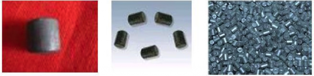
Cylpeds Size
- Doering International proposed the following expression when cylpeds are used as grinding media
- d↓B = 18.15 [(F↓80 / k) ↑0.5 (Ï↓s W↓i / 100φ↓C (3.281 D) ↑0.5) ↑0.33 ] mm
- When the estimated ball size is less than 25mm or the cylpeds size is less than 22 x 22 mm, it is estimated that the size should be increased 20% to 30%.
[images: (135-7-10)]
Ball Mill Size as a Replacement
- Grinding media wears and reduces in size at a rate dependent on the surface hardness, density and composition of the ore.
- Ball wear is directly proportional to surface area per unit mass and thus inversely proportional to ball diameter.
- Other factors include:
- Speed of mill rotation;
- Mill diameter;
- Mineral density;
- Work Index.
- Bond estimated the amount of wear in terms of kilograms per kWh based on the abrasion index, A;, i.e.,
- Wet Ball Mill = kg kWh = 0.16(Ai -0.015)0.33
- Dry Ball Mill = kg / kWh = 0.023Ai 0.5
Replacement Ball Size
- Rowland and Kjos proposed the use of their equation for the determination of the initial and replacement media size.
- Azzaroni (1981) and Dunn (1989) recommended the use of the following expression for the size of the makeup media:
d↓B – 6.3(F↓80) ↑0.29 (W↓i) ↑0.4 / (νD) ↑0.25Where ν = the rotational speed of the mill.
Ball Bulk Density
- Low density media can be used for soft and brittle materials.
- Hard materials required high density media.
- Rose and Sullivan (1961) estimated the required media density (ÏB) using the expression:
Ï↓B = (0.016Ï↓S↑2 + 20Ï↓S↑2) ↑0.5 – 0.4Ï↓s - Cast iron (ÏB = 4.3 – 4.8) and forged steel (ÏB = 4.6 – 4.8) are common materials used for media.
- Tungsten carbide media is used for very abrasive and hard ores (ÏB = 14.9).
- Pebbles and ceramic media (ÏB = 3.6) are adequate for soft materials.
Ball Size Distribution
- As the mill starts, grinding action and throughput increases.
- However, after reaching a critical speed, the mill charge clings to the inside perimeter of the mill.
- Under this conditions, the grinding rate is significant reduced or stopped.
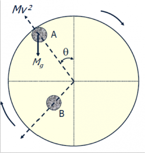
- All mills must operate less than Critical Speed
- At position A, the media is held to the wall due to the following force balance:
Mg cosθ = Mν↑2 / (R – r)g- R = Mill radius
- ν = linear mill velocity (m/s)
- M = Ball mass
- r = ball diameter
- g = gravitational acceleration
Critical Rotational Speed
- At θ=0 ° and cos θ = 1, the gravitational force pulling the media off the mill was maximized.
- Substituting and solving for speed rotational provides the expression for quantifying the critical velocity, vc:
ν↓C = 42.3 / √(D-d) revs/min - The above equation assumes no friction between the media and the liner.
- In practice, friction decreases with:
- Smoothness of liner
- Fineness of media
- Pulp density
- Abrasiveness of the material to be ground
- To modify the critical speed to account for friction:
- For dry grinding, multiply by 0.65.
- For wet grinding, multiply 0.70.
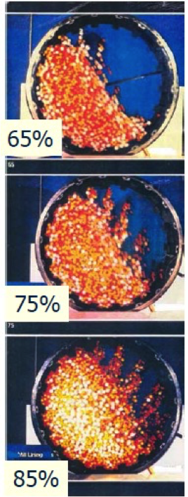
Mill Speed Impact on Optimum Breakage Condition
| % Critical Speed | Sliding | Cascading | Centrifuging |
|---|---|---|---|
| 10 | 3 | --- | --- |
| 20 | 3 | --- | --- |
| 30 | 3 | 1 | --- |
| 40 | 2 | 1 | --- |
| 50 | 2 | 1 | 1 |
| 60 | 2 | 2 | 1 |
| 70 | 1 | 3 | 2 |
| 80 | 1 | 3 | 2 |
| 90 | --- | 2 | 3 |
*Nordberg, 1970
Optimum speed to maximize impact breakage is 70% to 80% of critical speed.
Ball Charge Impact on Optimum Breakage Condition
| Ball Charge % by Volume | Sliding (all speeds) | Cascading | Centrifuging |
|---|---|---|---|
| 5-15 | 3 | --- | --- |
| 15-25 | 3 | 1 (high speeds) | --- |
| 25-35 | 2 | 2 (high speeds) | 1 (high speeds) |
| 35-45 | 1 | 3 (all speeds) | 1 (high speeds) |
| 45-50 | 1 | 2 (all speeds) | 3 (all speeds) |
*Nordberg, 1970
Optimum ball charge to maximize impact breakage is 35% to 45% of critical speed.
Mill Throughput Capacity
Mill capacity is a function of:
- Mill dimensions
- Type of mill
- Mill speed
- Mill loading
- Required particle size
- Feed size
- Work Index
- Mill shaft power
- Specific gravity of the rock
Bond developed an expression for capacity that accounts for each of these factors.
Mill Throughput Capacity
- Bond expressed mill capacity as a function of mill shaft power (PM, kW) and the energy required for particle breakage (kWh/f):Q = P↓M / E
- The expression for mill shaft power developed by Bond incorporates a number of operating parameters,
- The energy required for breakage was previously discussed, i.e.,E = W↓I(10 / √P↓80 – 10 / √F↓80
WI must be adjusted for nonstandard conditions
Mill Throughput Capacity (Austin et al., 1984)
- Austin et al. concluded that a single expression for capacity is not adequate for all mills.
- Equations for mill sizes less than 3.81meters in diameter and greater than 3.81meters were proposed:
t/h D < 3.81 m
t/h D > 3.81 m
- The factor CF is the correction for non-standard conditions including wet open circuit, wet closed circuit, wet and dry grinding, over size feed and under size grinding.
Mill Power Draw
- The motor power draw required to turn a mill from rest to the operating speed includes the energy required for the initial starting torque and mechanical arrangements to rotate the mill.
- It is generally accepted that practical mill power (PM ) is a function of mill capacity and diameter, i.e.,PM = Mill Constant * (Mill Diameter )n
where n = 0.3 to 0.5. - It is evident that mill power is a function of the height at which the media is lifted and the density of the media, i.e.,
PM = K Ïb LD2.5where k is a proportionality constant.
Mill Power Draw (Bond Method)
Based on a large number of observations, power draw was determined to be:
- Directly proportional to the mill length;
- A function of mill speed;
- A function of the total mass of the grinding media and rock charge;
- A function of the feed characteristics;
- A function of the work index of the material.
Bond developed an express ion to quantify mill shaft power based on data from a number of laboratory and industrial ball mills:
P↓S = 7.33J↓B Φ↓c (1-0.937J↓B)Ï↓b LD↑2.3 (1-0.1 / 2↑9 – 10Φ↓C)
ÏS = Mill power
D = Mill diameter in meters
L = Mill length in meters
ÏB = Ball density in t/m3
Wet Ball Mill Power Draw (Bond)
- For wet ball mills, Bond expressed power draw as a function of the total mass of media:P↓M / M↓B – 15.6Φ↓V (1 – 0.937 J↓B) D↑0.3 (1 – 0.1 / 2↑9 – 10Φ↓C) kW/t
M↓B = Ï€D↑2 / 4 J↓B Ï↓B (1 – Φ) - The bed porosity is typically in the range of 35% to 40%.
- In practice, the mill shaft power for wet overflow mills calculated using the above expression appeared to overestimate the actual power when:
- Maximum ball size, dmax < 45.7
- Mill inside diameter > 2400mm
Bond Wet Overflow Mill Corrections
- Corrections to counter the over estimation included in a slump factor, Fs:F↓S = 1.102 (45.72 – d↓max / 50.8) kWtThe Fs factor is subtracted from the calculated power draw.
- The ball size factor, FB, is added to the mall shaft power for mill sizes greater than 3.3 meters:F↓B – 1.102 (d↓max – 12.5D / 50.8) kW/t
Other Rowland & Kjos Power Draw Corrections
- F1 : Dry grinding correction
- F2 : Correction for wet open circuit since it requires more power than wet closed circuit.Based on the sieve size used to determine the work index and the percentage of the product passing this size.
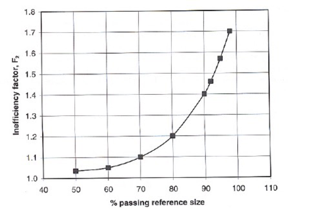
Power Draw Corrections [image: 135-7-14)] - F3: Correction for material in the feed that is greater than the optimum size, F0S:
F↓0S = 4000[13 / W↓I] ↑0.5
F↓3 = 1+1 / R[W↓i – 7] [F↓80 / F↓0S – 1] - F4: Correction when the product size is less than 75 microns:
F↓4 = [P↓80 + 10.3 / 1.145P↓80] - F5: Correction when the reduction ratio is less than 6:
F↓5 = 1+0.13 / (R – 1.35)
Mill Dimension Design
- Ore: limestone
- Throughput: 250 Tph
- F80 = 10mm
- P80 = 0.1mm
Calculate the mill size required to handle the desired throughput:
Solution:
W = 10*11.25(1/√100 – 1/√100 0) kWt/t = 10.125 kWh/t
Mill Dimension Design Example
Example: PM = 250 * 10.125 = 2531 kW
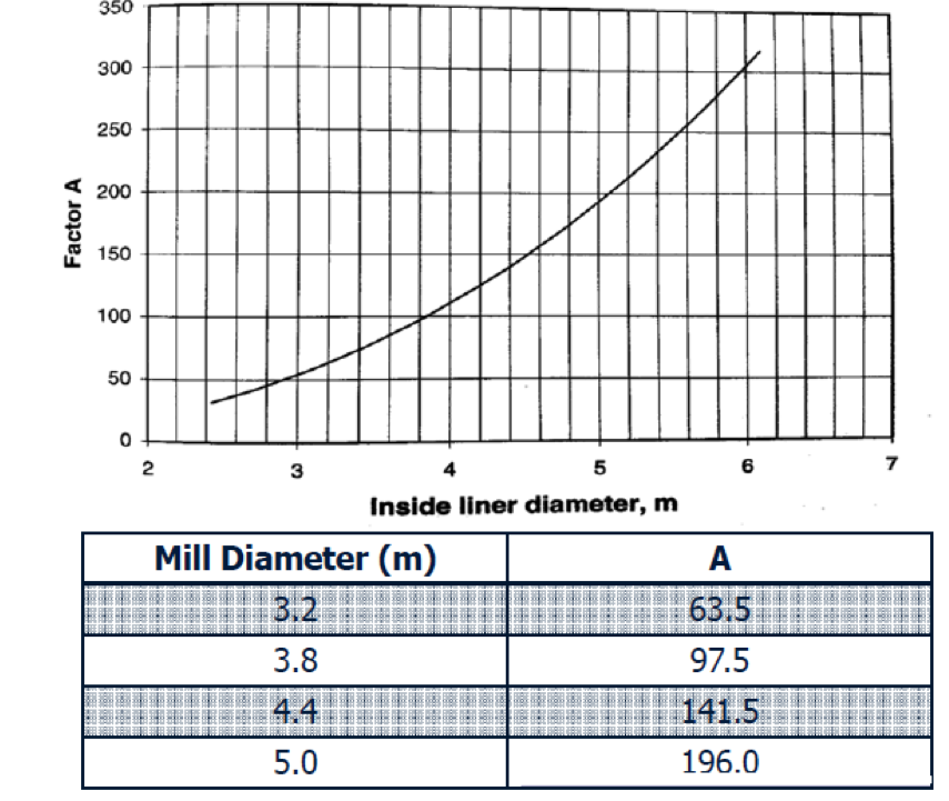
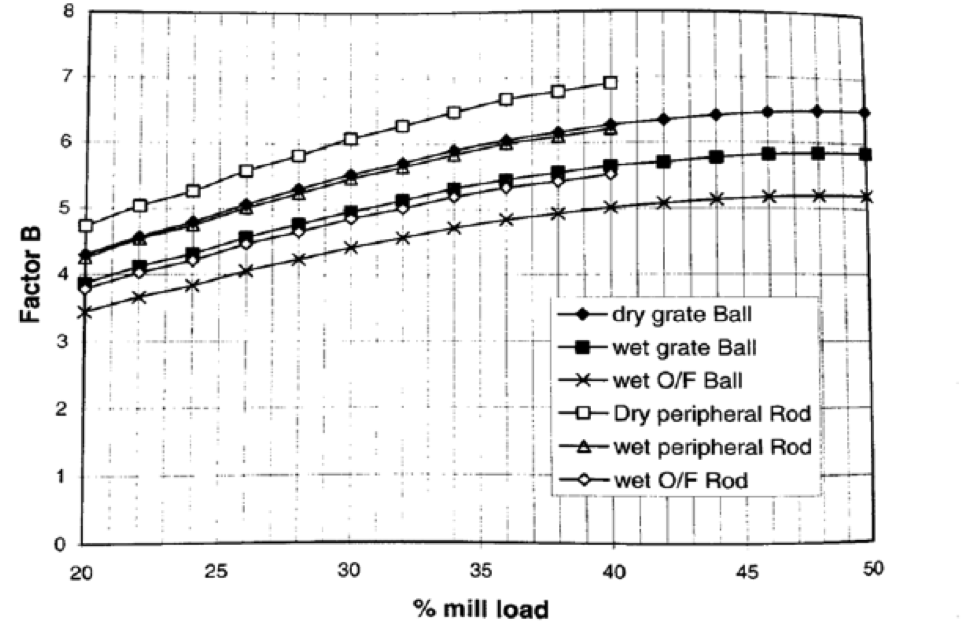
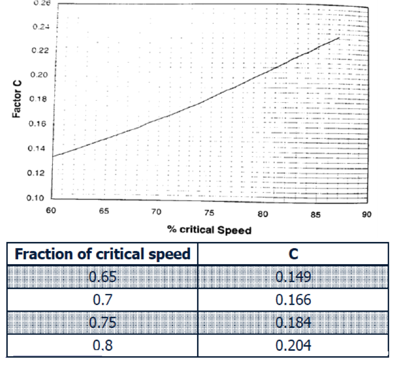
The Nordberg Method: PM = 2.448 ABCL
where
- A = Mill diameter factor
- B = % charge loading factor
- C = mill speed factor
- L = Length of mill
Mill Power Consumption Example
- Ball mill = 3.5 m x 3.5 m
- Rubber lining = 75 mm
- % Mill volume charge = 40%
- Grinding balls diameter = 70 mm
- Mill operational speed = 17.6
Calculate the optimum power consumption to operate the mill.
Solution:
P↓M / M↓B = 15.6Φ↓C (1 – 0.937 J↓B) D↑0.3 (1 – 0.1 / 2↑9-10Φ↓C) kWt
M↓B = Ï€D↑2 / 4 J↓B Ï↓B (1 – Φ)
- Actual mill diameter = 3.5-2 * 0.075 = 3.35
- Critical Speed
- ν↓C = 42.3 / √(D-d) rpm = 23.4
- ΦC = (17.6 / 23.4_ * 1000 = 0.75
- PM / MB = 10.14 kW/t
- With ball density = 7.8 t/m3
- MB = 57.75 t
- Slump correction factor check:
- D > 2.4 m but d > 45.7 mm, so no slump correction required
- Ball size correction factor check:
- D > 33.3 m, so a ball size correction factor should be applied
F↓B = 1.102 (d↓max – 12.5D / 50.8) kWt/t = 0.010 kW/t
- D > 33.3 m, so a ball size correction factor should be applied
- So corrected PM / MB = 10.14 + 0.610 = 10.75 kW/t
- Total power – 10.75 kW/t * 57.75 t = 621 kW