Contents
Objectives
At the end of this lesson students should be able to:
- Explain the grinding process
- Distinguish between crushing and grinding
- Compare and contrast different type of equipment and their components used for grinding
- Identify key variables for process control
- Design features of grinding equipment (SAG, BALL and ROD MILLS)
- Explain typical flowsheets of grinding circuits involving single or combination of equipment
Reading & Lecture
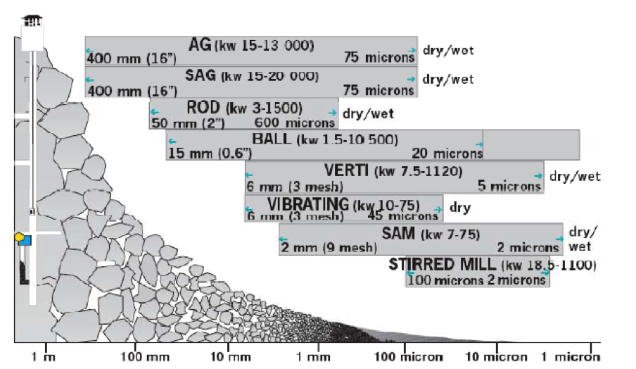
Size reduction by crushing has a size limitation for the final products. If further reduction is required, below 5- 20mm, grinding processes should be used.
Grinding is a powdering or pulverizing process using the rock mechanical forces of impaction and attrition.
The two main objectives for a grinding process are:
- To liberate individual minerals trapped in rock crystals (ores) and thereby open up for a subsequent enrichment in the form of separation.
- To produce fines (or filler) from mineral fractions by increasing the specific surface.
Grinding takes place in more “open” space which makes the retention time longer and adjustable compared to crushers.
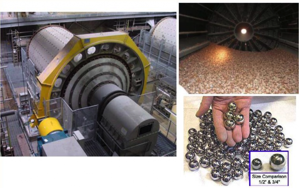
[image: (135-6-1)]
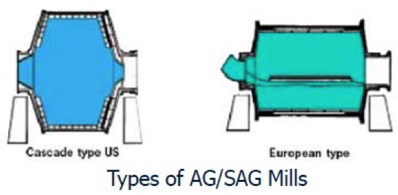
AG/SAG Mills
Autogenous Grinding (AG) Mill
- Wet or dry
- Primary, coarse grinding (up to 400 mm feed size)
- Grinding media is grinding feed
- High capacity (short retention time)
- Sensitive to feed composition (critical size material)
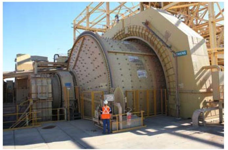
Semi-Autogenous Grinding (SAG) Mill
- Wet or dry
- Higher capacity than A-G mill grinding
- Primary, coarse grinding (up to 400 mm feed size)
- Grinding media is grinding feed plus 4-12% ball charge (ball dia.100- 125 mm)
- High capacity (short retention time)
- Less sensitive to feed composition (critical size material)
Semi-Autogenous Mill
[image: (135-6-2)]
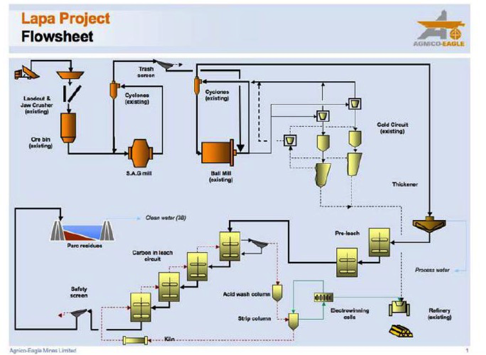
SAG Mill Circuit Example — Gold Processing
[image: (135-6-3)]
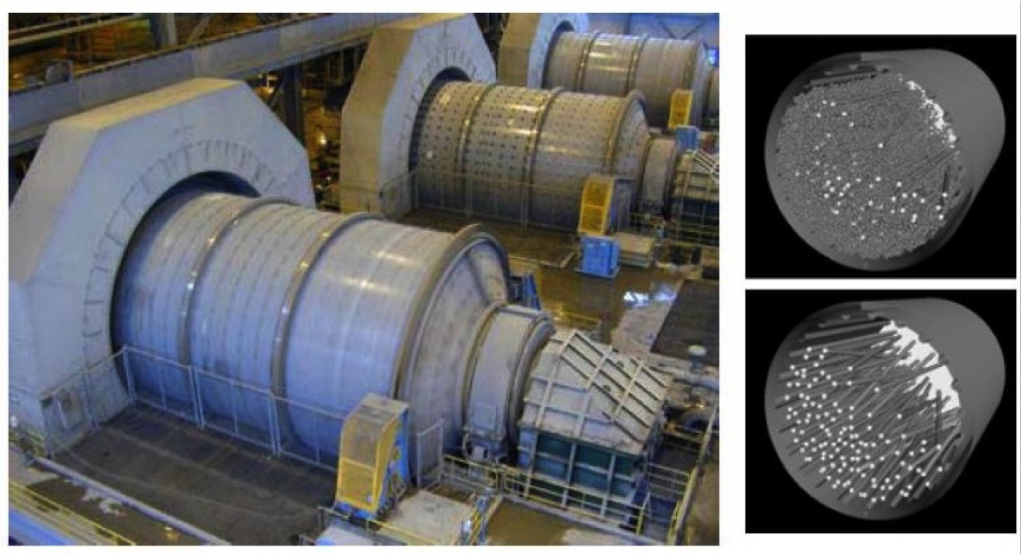
AG/SAG Mill
- AG/SAG mills are normally used to grind run-off-mine ore or primary crusher product.
- Wet grinding in an AG/SAG mill is accomplished in a slurry of 50 to 80 percent solids.
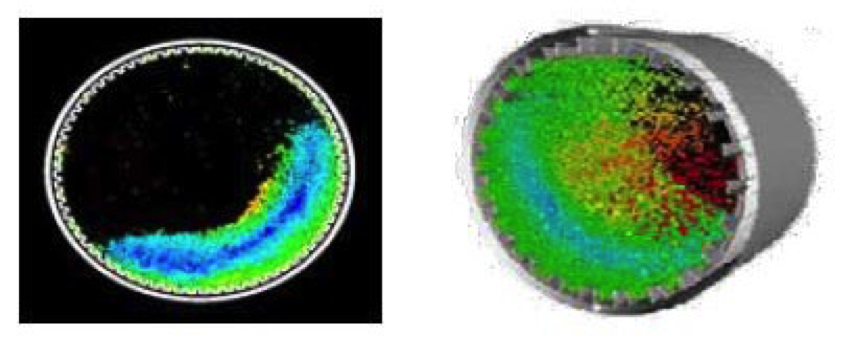
red=fastest, blue=slowest moving particles
[image: (135-6-4)]
- The mill product can either be finished size ready for processing, or an intermediate size ready for final grinding in a rod mill, ball mill or pebble mill.
- AG/SAG mills can accomplish the same size reduction work as two or three stages of crushing and screening, a rod mill, and some or all of the work of a ball mill.
- Because of the range of mill sizes available, AG/SAG milling can often be accomplished with fewer lines than in a conventional rod mill/ball mill circuit.
[image: (135-6-5)]
Rod Mills
- Wet only
- Coarse grind
- Primary mill at plant capacities of less than 200 t/h
- Coarse grinding with top size control without classification
- Narrow particle size distribution
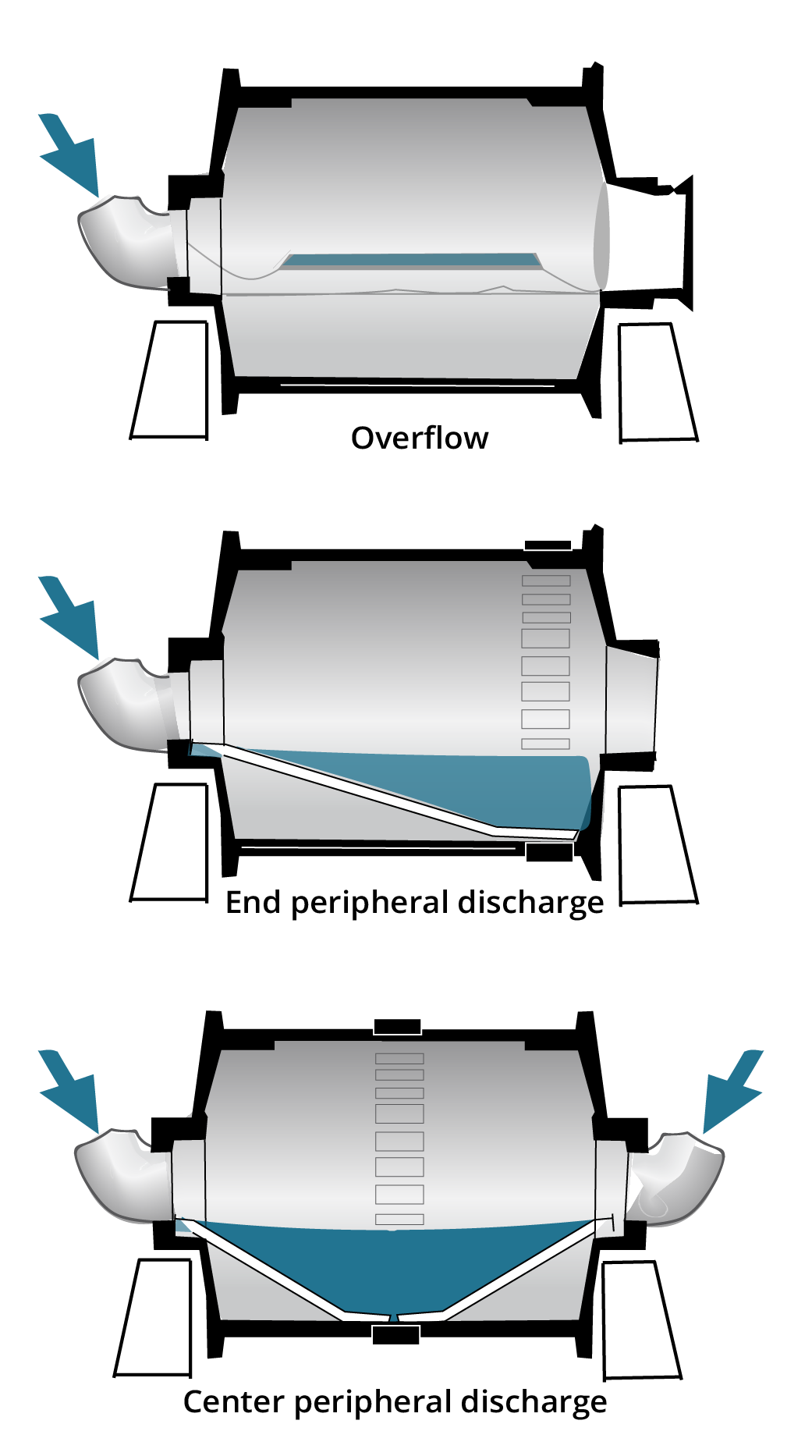
- Mostly dry
- Coarse grind high capacity
- Special applications
- End discharge: finer product
- Centre discharge: rapid flow, less fines
- Narrow particle distribution
Grate discharge is not available in Rod Mills
[image: (135-6-7)]
Rod Mill Comparison
[image: (135-6-8)]
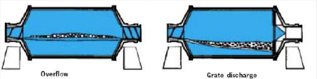
Overflow
- Wet only
- Robust and simple
- Finer grind (longer retention time)
- High risk for over grinding
- Ball charge 35-45%
Discharge
- Discharge end more complicated
- Coarser grind (shorter retention time)
- Lower risk for over grinding
- Can take about 5-10% more ball with corresponding higher throughput
[image: (135-6-11)]
Pebble Mill

[image: (135-6-13)]
- Wet or dry
- Always grate discharge
- Secondary grinding
- Grinding media :
- A size fraction screened out from feed
- Flint pebbles
- Porcelain balls
- Al203 balls
- Larger than Ball mills at same power draw
Special Tumbling Mill
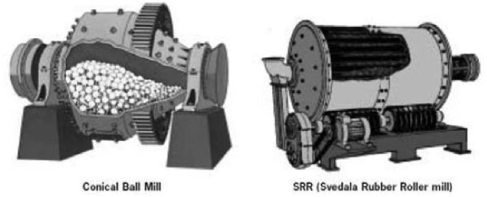
[image: (135-6-14)]
- Wet or dry (air swept)
- Overflow or partial grate
- Conical shell for “graded” ball charge and optimal size reduction
- Only available in small and intermediate sizes
- Efficient “high reduction ratio grinding’
- Wet or dry
- Overflow and grate discharge
- Light and fabricated construction
- Ready assembled on steel frame
- Easy to move
- Limited in size (max. diameter 2.4 m)
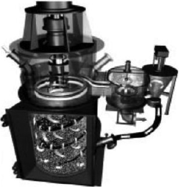
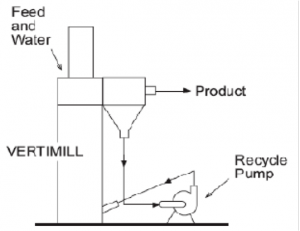
Vertimill ® (Metso Minerals)
- Wet grinding only
- Top or bottom feed
- Grinding by attrition/abrasion
- Primary or regrinding mill
- Ideal for “precision” grinding on finer products
- Restriction in feed size (6mm)
- Restriction in energy (1119 kW/ 15oo hp)
- Ball size max. 30mm
[image: (135-6-16)]
Stirred Mills vs. Tumbling Mills
Advantages of Stirred Mills (VERTIMILL ®):
- Lower installation cost
- Lower operation cost
- Higher efficiency
- Less floor space
- Simple foundation
- Less noise
- Few moving parts
- Less overgrinding
- Better operation safety
Typical Cost of Grinding
- The main costs for grinding are energy, liners and grinding media.
- They are different for different mill types. For tumbling mills:
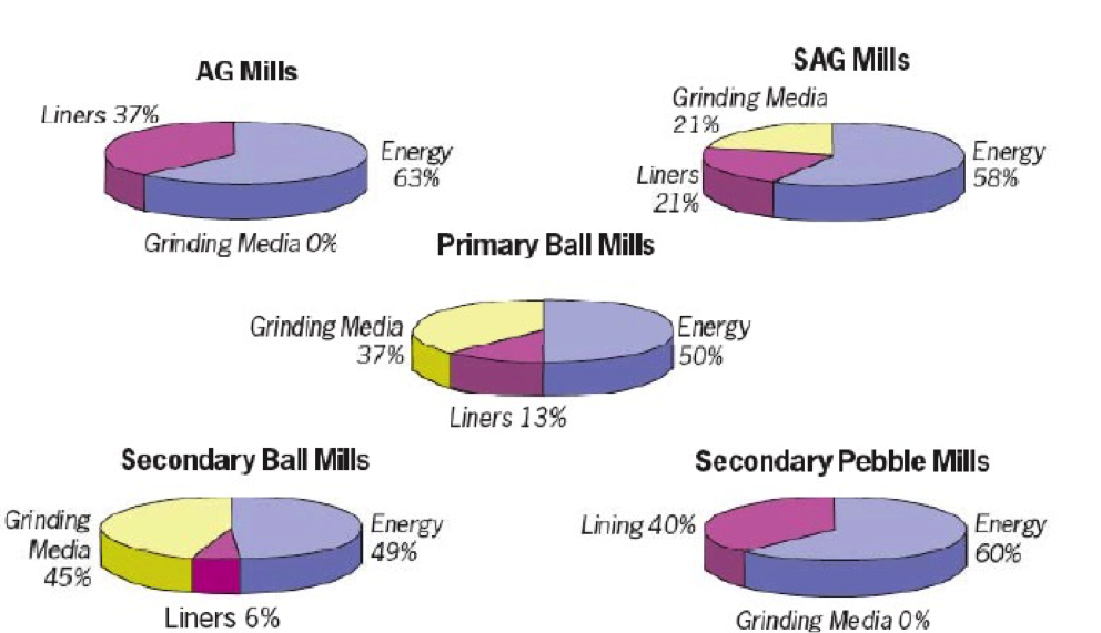
[image: (135-6-17)]
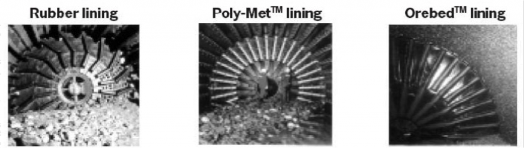
Basic Mill Linings
- Use rubber linings wherever possible due to lifetime, low weight, easy to install and noise dampening.
- When application is getting tougher use steel-capped rubber, still easier to handle than steel.
- When these both options are overruled (by temperature, feed size or chemicals) use steel.
- Ore-bed is a lining with rubber covered permanent magnets used for special applications like lining of VERTIMILLs, grinding of magnetite
[image: (135-6-18)]
Size Grinding Mills
Fundamental to all mill sizing is determining the necessary specific power consumption for the grinding stage (primary, secondary, tertiary etc.) .
It can be established (in falling scale of accuracy) in one of the following ways :
- Operating data from existing mill circuit (direct proportioning) .
- Grinding tests in pilot scale, where the specific power consumption is determined (kWh/t dry solids) .
- Laboratory tests in small batch mills to determine the specific energy consumption.
- Energy and power calculations based on Bonds Work Index (Wi, normally expressed in kWh/ short ton).
- Other established methods, for instance Hardgrove Index, population balance.
Scale Up in Sizing for Grinding Mills
- Scale-up criterion is the net specific power consumption, i.e. the power consumed by the mill rotor itself minus all mechanical and electrical losses divided by the feed rate of solids.
- For the full scale mill, specific power is multiplied by the feed rate to get the net mill power. This must then be increased by the anticipated mechanical inefficiencies (bearing/gear friction losses and possible speed reducer losses) as well as electrical losses, in order to arrive the gross mill power.
- For all AG or SAG installations, batch lab tests are mandatory to determine whether this type of grinding is possible at all, as well as establishing the necessary specific power consumption.
Size Reduction Circuits
Single Stage AG Mill
For the rare cases where primary AG milling will inherently produce the required product size. (Wet and dry)
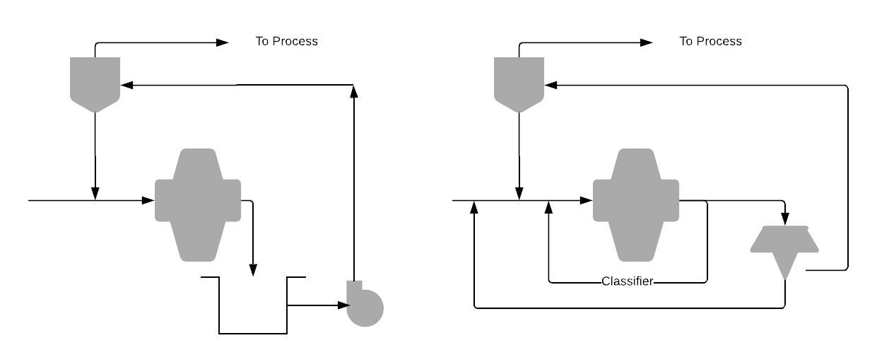
AG Mill + Crusher
For the cases where critical size fractions needs to be removed from the mill and crushed separately to prevent overgrinding. Resulting size must match product requirements.
[image: (135-6-19)]
AG Mill + Ball Mill + Crusher (ABC Circuit)
- This can be used to correct a too coarse product from the primary mill.
- Mostly operated wet, but also dry possible.
AG Mill + Pebble Mill
- Two stage AG-grinding with the primary mill in open circuit and the secondary pebble mill in closed circuit.
- The pebbles screened out from the primary mill or recirculated to the primary mill based on size.

[image: (135-6-21)]
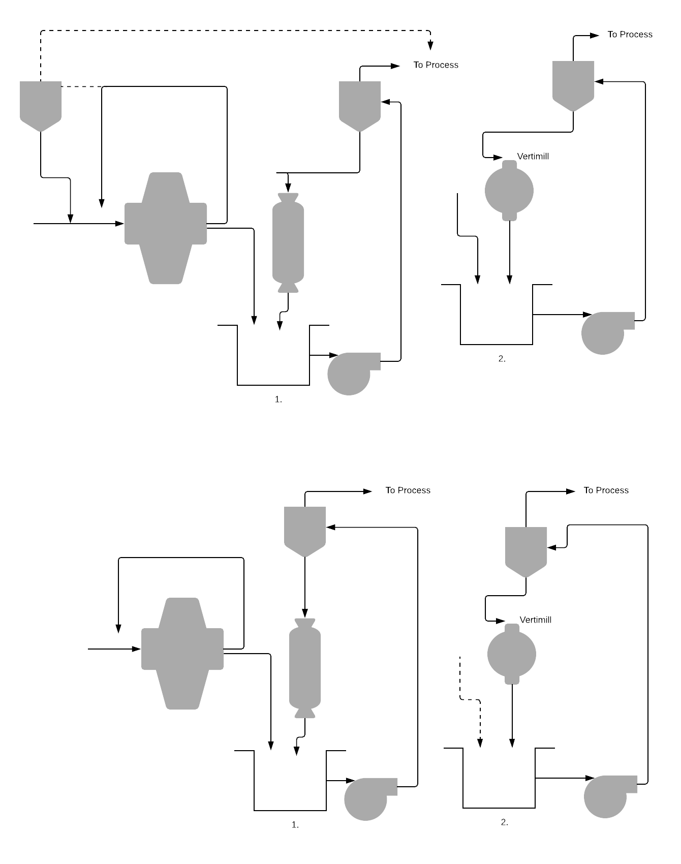
AG Mill + Ball Mill / Vertimill
- Pebble mill is replaced by a ball mill or a Vertimill in the previous circuit.
- This is used when there is not enough pebbles available in the circuit, or all autogenous grinding produces too much fines
AG Mill + Ball Mill / Vertimill
- Pebble mill is replaced by a ball mill or a Vertimill in the previous circuit.
- This is used when there is not enough pebbles available in the circuit, or all autogenous grinding produces too much fines
[image: (135-6-23)]
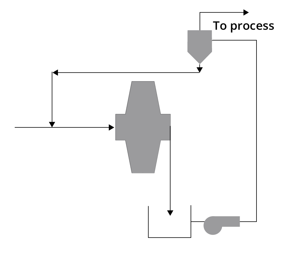
Single Stage SAG Mill
- Using SAG instead of AG increases the capacity as well as application range, but will also increase wear costs and still be dependent on “natural” product size being close to the desired.
- Common circuit in the US and Canada
[image: (135-6-25)]
Closed Vertimill Circuit with Integral Classifier
- Used for wet circuits with not too fine desired product and/or not stringent coarse end oversize of the product.
- Max. feed size – 6 mm (1/4″).
[image: (135-6-26)]