Contents
Objectives
- Define ‘temperature’ and related terms
- Identify common types of Temperature instrumentation
- Perform temperature and pressure conversion calculations
- Review Temperature instrumentation symbols on PID’s
Reading
Temperature — Terms to Know
- Sensor — will respond to the process variable
- Temperature
- Heat Transfer, Conduction, Convection, Radiation
- Phase Change, Heat of Vaporization
- Latent Heat, Sensible Heat
- BTU
- Fahrenheit/Rankine; Celsius/Kelvin
- Absolute Temperature
Heat Transfer Terms
Convection
- Mixing two substances or direct contact with one substance (exhaust gases)
- hot coffee and cold cream
- Convection oven — blows hot air around food
Conduction
- Contact through a solid — no mixing; indirect contact
- Shell/tube heat exchangers
- Pan on electric stove top — pan conducts heat from burner to food
Radiation
- Electromagnetic waves — no contact
- Sunshine, heat from woodstove, burner flames in furnace
- Pan under a broiler — radiant heat from burner/flame onto food
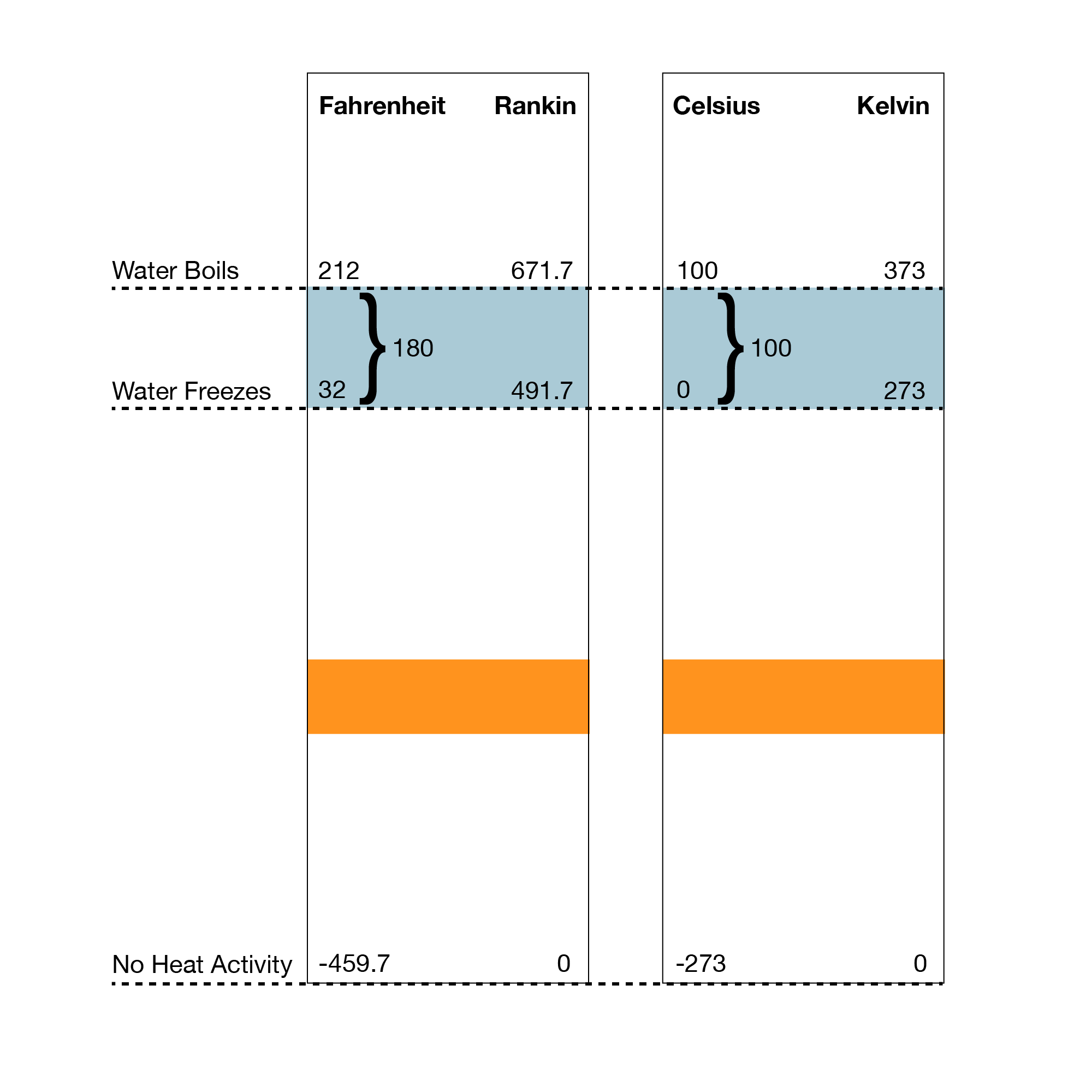
Absolute Temp/Pressure
Absolute temperature — temperature scale where 0 = ‘absolute zero’ – the temperature where no more heat can be removed from a system. This corresponds to 0 K or -273.15 °C. Theory — no more molecular movement.
Absolute pressure – pressure measured from 0 = full vacuum. 0 psia = full vacuum
Gauge pressure – pressure measured from 0 = current atmospheric pressure. 0 psig = atmospheric pressure
Temperature Scales vs. Actual Temperature
Absolute Temperature:
(Kelvin) K = C + 273
(Rankin) R = F + 460
F = (C x 9/5) + 32
C = (F-32) x 5/9
K = R x 5/9
R = K x 9/5
[image 140-3-01-01]
Latent Heat vs Sensible Heat
- Sensible Heat — heat that can be ‘sensed’ by a thermometer — i.e. the temperature changes
- Latent Heat — heat that cannot be ‘sensed’ by a thermometer — i.e. temperature doesn’t change when phase is changing.
- Boiling water stays at 212 F until all of it is steam — even while we keep adding heat. This is called the latent heat of vaporization.
- Same idea when water freezes — releases latent heat.
Temperature Instruments
- Thermowell
- Thermometer
- BiMetallic Strip
- RTD — Resistance Temperature Device
- Thermocouple
- Thermistor
- Temperature Gauge
Thermowell
- Not an instrument — it holds the instrument and protects it from the process, while allowing heat transfer
- TW

[image 140-3-02]
Thermometer
- Glass Bulb — standard
- Also IR — Infrared — non-contact
[image 140-3-03]
BiMetallic Strip
- Two Dis-similar metals, bonded together
- Expansion/Contraction with Temperature different for 2 metals
- Movement of strip, moving temperature dial
- Dial thermometer very common

[image 140-3-04]
RTD — Resistance Temperature Device
- Electrical resistance (ohms) will change with temperature — varying output signal
- More accurate than Thermocouple
- Smaller operating range (-200F to 900F)
- Ohms resistance in the RTD correlates to temperature — see tables
100 (1000) Ohm Platinum RTD Resistance Chart
Generally RTDs are a 3- or 4- wire configuration — fine electrical wires

[Image 140-3-06]

[image 140-3-07]
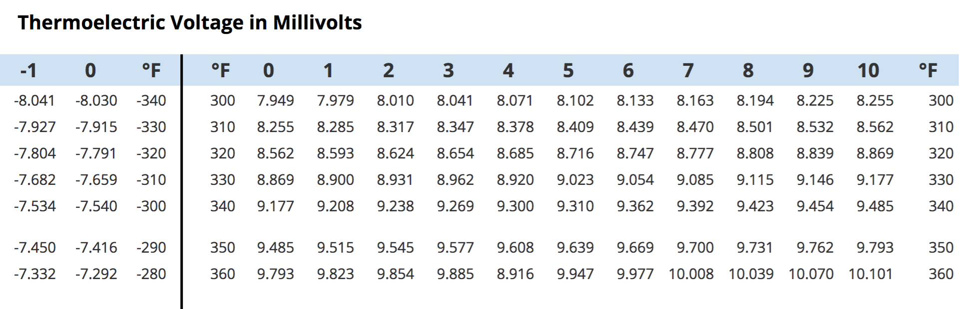
Thermocouple
- Most common, simplest
- Two dissimilar metals — generate voltage at their junction when they are heated.
- Measured junction — connects to process
- Cold junction/reference — connects to transmitter
- mV generated across Thermocouple correlates to temperature — see tables
[image 140-3-08]
Thermocouples
- Generally 2-wire configuration
- Wires are thicker
- made of the dissimilar metals

[140-3-9]
Thermistor
- Ceramic resistor — same principle as RTD —
- Electrical resistance through thermistor changes with temperature
- Usually small bead/disk
- Registers very small temperature differences
Temperature Gauge
No transmitter — gauge face (like PI)

[Image 140-03-11]
Temperature transmitters — How to identify them in the field
- Read the nameplate on the instrument
- Should include calibration range
- Will include model number — can look it up
- May include facility tag number
- Look at how it’s connected to the process
- Temperature sensors almost always have THERMOWELLS to house the sensor
- Temperature sensors usually extend into the process stream — so there will NOT be an isolation valve on the process connection.
Temperature Conversion Calculations
- Absolute: (Kelvin) K = C + 273
- Absolute: (Rankine) R = F + 460
- F = (C x 9/5) + 32
- C = (F-32) x 5/9
Temperature Conversion
32 C = ?? F
F = (C x 9/5) +32
F = (32 x 9/5) + 32
F= 89.6
32 C = 89.6 F
25 F = ?? C
C = (F-32) x 5/9
C= (25-32) x 5/9
C= -3.9
25 F = -3.9 C
25 C = ?? F
F = (C x 9/5) +32
F = (25 x 9/5) + 32
F = 77
25 C = 77 F
100 C = ?? K
K = C + 273
K = 100 + 273
K = 373
100 C = 373 K
Temperature ‘linear scaling’ – NEW
The conversions between F and C temperature scales are an example of how we use the linear scaling calculation.
We looked at this equation in week 1 — it seems very complicated:
VALUEB = {[(VALUEA — LRVA)/SPANA] x SPANB} + LRVB
But it’s not, and you’ve been doing it already:
LRV = lower range value = the lowest value in the operating range
URV = upper range value = the highest value in the operating range
Span = URV — LRV
We pick two equivalent operating ranges:
Temperature — range from freezing to boiling:
Convert any C reading to F
(Whenever we get data, that set of units becomes the “A’ data)
F = {[(C reading — 0 C)/100 C] x 180 F} + 32 F
This equation is mathematically equivalent to:
F = (C X 9/5) + 32
Try it out! Convert 140 °C to F
F = {[(C reading — 0 C)/100 C] x 180 F} + 32F
F = {[(140C — 0C)/100C] x 180F} + 32 F
F = {[140C/100C] x 180 F} + 32 F
F = {1.4 x 180 F} + 32 F
F = 252 F + 32 F
F = 284 F
140 C = 284 F
F = (C X 9/5) + 32
F = (140 x 9/5)+32
F = (252) + 32
F = 284
140 C = 284 F
Linear Scaling Calculation
VALUEB = {[(VALUEA — LRVA)/SPANA] x SPANB} + LRVB
The linear scaling calculation is used to relate all kinds of linearly related scales. For example:
- Operating temperature range will be 200 F to 600 F
- We want the 4-20 mA signal from the transmitter to reflect that range.
We can use the scaling calc to calculate the mA reading at any temperature in the range — try 440 F.
F: LRV=200 F URV= 600 F Span = 400 F
mA: LRV = 4 mA URV = 20 mA Span = 16 mA
mA = {[(440F — 200F)/400F] x 16 mA} + 4 mA
mA = {[240F/400F] x 16 mA} + 4 mA
mA = {0.6 x 16mA} + 4 mA
mA = 9.6 mA + 4 mA = 13.6 mA at 440 F
Process Variable Relationships
Pressure, Volume, Temperature in a closed container
Pressure/Temperature are in Absolute Units
T = K,R P = psia
V1, V2 both in the same units