Objectives
- Define basic controller terms — overview
- Outline the common controller settings
- Identify physical configurations for controllers
- Describe final control elements
- Identify components
- Identify applications
Terms to Know
- Control valves: ATO, ATC
- Control Valve failure modes — FC, FO, Fail-Last
- Controller Action: Direct vs Reverse
- Local/Remote Controllers (location)
- Local/Remote Control/Setpoint (where SP comes from)
- Streams: Manipulated vs. Controlled vs. Measured
- Bump — Bumpless Transfer
- Controller Modes: Integral/Derivative – definitions
- Proportional Band/Proportional Gain – calculations
- Controller/Control Scheme configurations:
- Cascade/Split-Range/Ratio
Analog Controllers
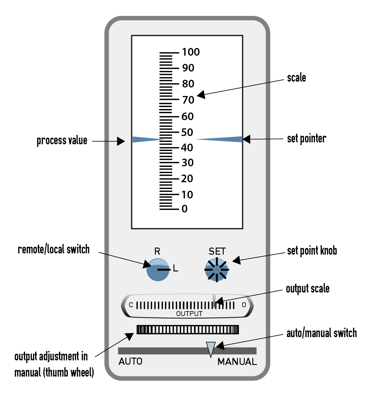
[140-12-01a]
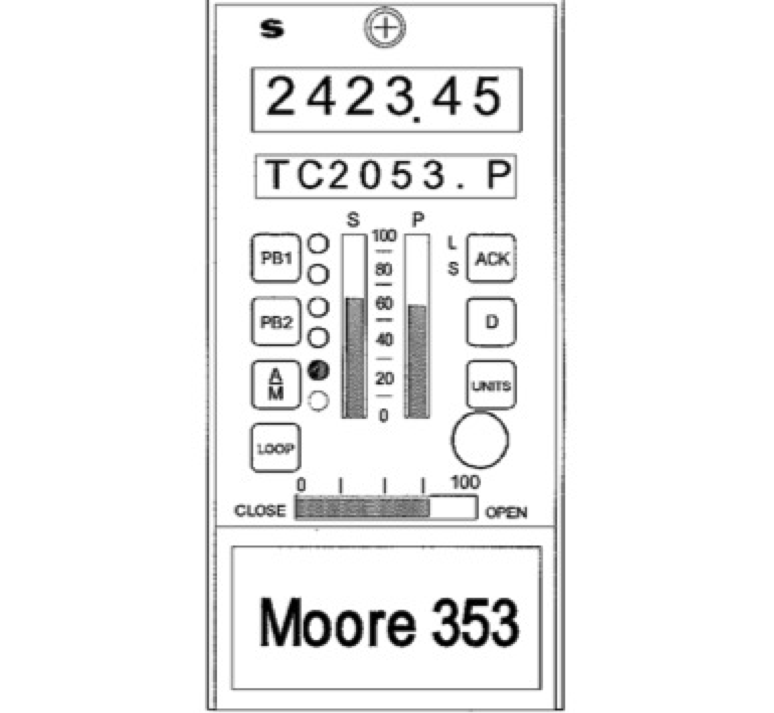
Image [140-12-01b]
Controllers – Terms to Know
- Direct Action
- Increased Input = increased output
- Reverse Action
- Increased Input = decreased output
- If Output signal = valve opener — think of scenarios for direct/reverse action
- Level control
- Flow Control
Auto/Manual Bumps
- Auto/Manual — Bumpless Transfers
- Bump — controller output changes dramatically because of a switch from auto/manual, manual/auto — can cause a Process Upset
- Bumpless transfer from manual to automatic
- Adjust SetPoint to match current Process Value
- Switch manual to auto
- Monitor for drift
- Reset the SetPoint if it’s not where you want it
Controller Modes
(You’ll work with this more in the future… definitions only)
- How the output signal responds to input signals, how smoothly the control functions
- Integral Action
- Figures time into the equation — how long has PV been different from SP
- Control is working to ‘reset’ to the process setpoint
- Derivative Action – RATE
- Figures rate of change into the equation — how fast is PV moving away from SP
- Integral Action
(Know calculations here)
- Proportional Band and Gain
- How much a change in input affects a change in output — how big a response is needed for a change in PV
- Example: How does steam output respond to fuel input?
Process Gain, Proportional Band Calcs
- Process Gain =
- Dimensionless, can be positive or negative
- Δ = final – initial
- Proportional Band – (1/GAIN) x 100%
%
- A percentage, use absolute value
Questions for Consideration
- What is Δ output / output transmitter span ?
- How can you change the gain or PB on a control loop?
- Why?
Calculate Process Gain
- Fuel flow to a boiler is adjusted in order to control the volume of steam produced.
- Fuel flow transmitter is calibrated from 45 gpm — 375 gpm.
- Steam flow transmitter is calibrated from 3,000 lbs/hr — 10,000 lb/hr
- If the fuel flow is changed from 75 gpm to 100 gpm, the steam production rate changes from 4,000 lb/hr to 4,300 lb/hr.
- Input = ?? Output = ??
- Variables needed:
Change in input (new — old) or (final — initial) Change in output (new — old) or (final — initial) Input transmitter span (URV-LRV) Output transmitter span (URV-LRV)
Input Fuel; Output Steam
- Change in output = 4300 lb/hr – 4000 lb/hr = 300 lb/hr
- Change in input = 100 gpm – 75 gpm = 25 gpm
- Output span = 10,000 lb/hr – 3,000 lb/hr = 7,000 lb/hr
- Input span = 375 gpm – 45 gpm = 330 gpm
- What are the units?
Types of Controllers to Know
- Physical location
- Local controller
- Remote controller
- Setpoint origin — remote vs local setpoint
- Type of control scheme – Both the programming and the physical setup
- Split Range
- Cascade
- Ratio
Controlled Stream vs. Manipulated Stream
- Discussion: Is the ‘controlled’ stream the same as the ‘manipulated’ stream?
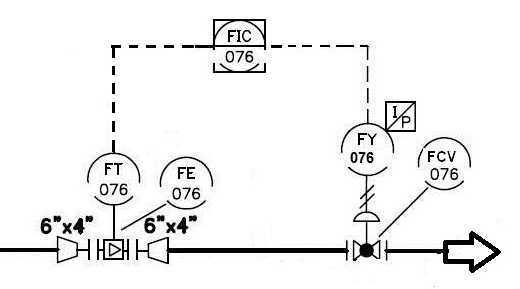
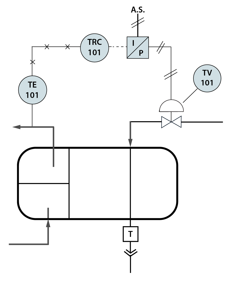
Image [140-12-02b]
Split Range Control
One controller, two control elements
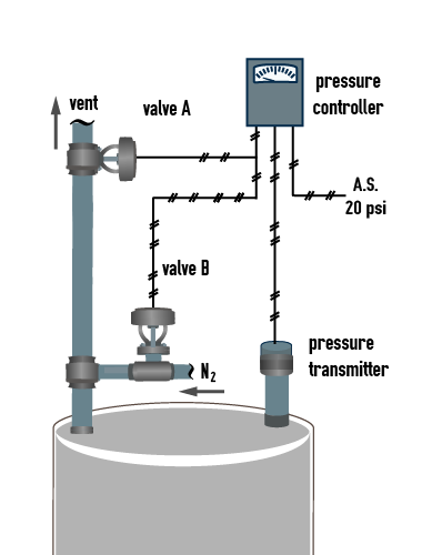
Image [140-12-03]
- Split range requires two final control elements
- Each FCE responds to a portion of the controller output signal
- Typical application: Tank blanketing system — needs to vent OR pressurize, depending on current pressure in tank
Cascade Control
Two controllers, on control element
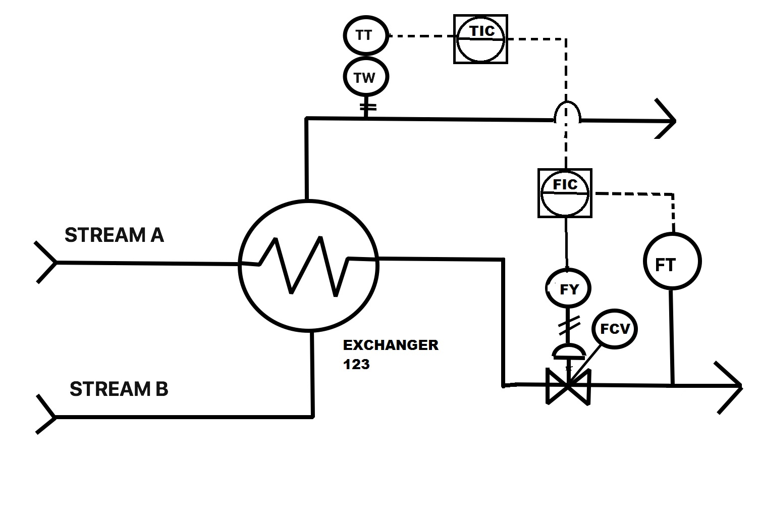
[image 140-12-04]
- Output of one controller = remote setpoint for another controller
- TIC- Temperature Indicating Controller – Primary Controller
- Secondary (flow) controller receives setpoint from the Primary Controller
- This scenario — control temperature on Stream B outlet by changing flow setpoint on Stream A in.
- Option for secondary Controller to operate on a local setpoint
- Secondary controller affects the value of the primary variable
Why not just do this?
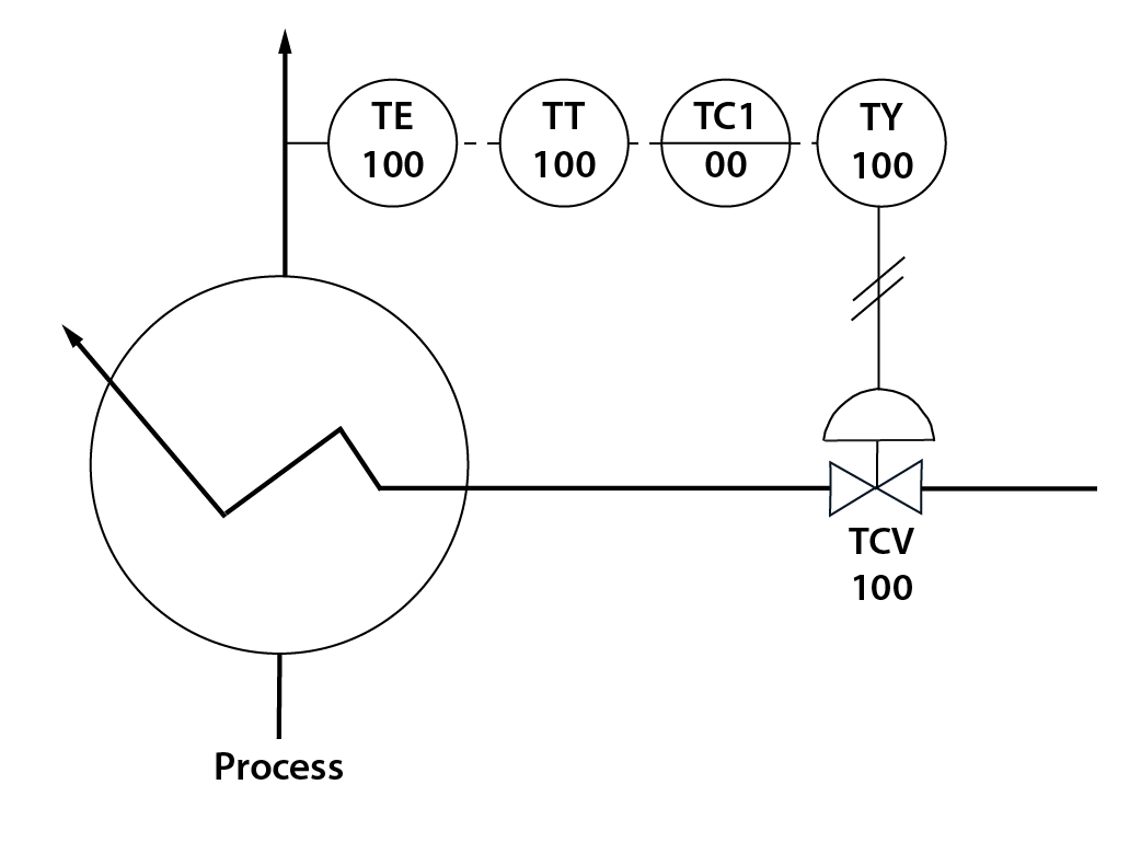
Image [140-12-05]
- Better control
- Reduced lag times
- Need to control the flow rate separately under certain conditions, etc.
Ratio Control
2 controllers, 1 or 2 control elements
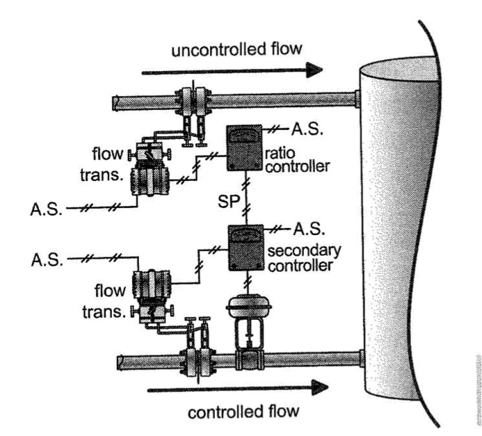
Image [140-12-06]
- Proportion one flow based on another
- Which is the primary transmitter?
- Note which flow is controlled vs. which flow is measured vs. which flow is manipulated..
- Note that the secondary controller does not affect the value of the primary variable — it responds to it
Final Control Elements
- Valves — most common, used in this class
- Louvers, Dampers
- Ex.:Change position to manipulate air flow
- Motors
- Can have variable speed drives, which change the output of the associated pump/compressor, etc.
Valve Operation – Overall
- ATO — Air To Open — Fail Closed
- As 3-15psig signal increases, valve opens
- Loss of air = valve slams closed
- ATC — Air To Close — Fail Open
- As 3-15 psig signal increases, valve closes
- Loss of air = valve slams open
- Fail Last, Fail-In-Place
- Operates differently
- Loss of air = valve stays where it was
Activity
If the level gets too high (goes over the setpoint, sending an increasing signal to the controller), the control valve starts to open, to drop the level in the tank. If the control vale is ‘air-to-open’, does it take an increasing or decreasing signal to open it? Given that, is the LIC a reverse-acting or direct-acting controller?
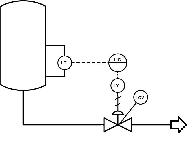
[Image 140-12-07]
Surprise! I can solve this with a table:
Set up Instrument Loop Analysis Chart
- Include the actual controlled process value on the beginning, final manipulated process value at the end.
- Instruments in order, tracing through the signal path.
Identify any ‘actions’ or ‘valve fail-safe’ configurations known (i.e. reverse/direct, ATO/ATC)
- If action is not discussed, or we haven’t discussed reverse/direct for that type of instrument, leave blank
- Note that valve fail-safe positions (marked on PID) lead to the ATO/ATC designation
Set up columns for well below setpoint (minimum process value), process value at setpoint, and process value well above setpoint (maximum process value).
- You may want intermediate spots, as well, to illustrate more complicated schemes.
Fill in the data you know, based on a description of how the loop functions.
- At each point, consider how the system needs to RESPOND to head towards the setpoint.
Step through from instrument to instrument, filling in blanks that make sense.
- You may be working from both ends of the loop — just move through it very orderly
When complete, read through the whole chart to see if it makes sense, based on a description of what’s happening.
Fill In What Is Known
| Component/Step | ACTION - dir/rev/NA or ATO/ATC/other | Position or Signal at lowest PV | Position or Signal at PV SP | Position at highest PV |
|---|---|---|---|---|
| Process value - Level in tank 5 | ||||
| LT-100 | ||||
| LC-100 | ||||
| LY-100 | ||||
| LCV-100 | ||||
| Process value - flow of steam out |
Solution
| Component/Step | ACTION - dir/rev/NA or ATO/ATC/other | Position or Signal at lowest PV | Position or Signal at PV SP | Position or Signal at highest PV SP |
|---|---|---|---|---|
| Process value - Level in tank 5 | NA | Level = too LOW | Level = Just right | Level = too HIGH |
| LT-100 | Direct | 4 mA | Middle | 20 mA |
| LC-100 | Direct - Figured from looking at signal in from LT to signal out to LY | 4 mA | Middle | 20 mA |
| LY-100 | NA (yet) | 3 psig | Middle | 15 psig |
| LCV-100 | ATO | Closed | Middle | Open |
| Process value - flow of stream out | Flow = Low | Flow = just right | Flow = High |