Contents
Objectives
- Define pressure and formula P=F/A
- Define terms associated with pressure and pressure instruments, per textbook
- Identify common types of pressure-sensing/measuring instruments used in the process industry:
- manometers
- pressure gauges
- differential pressure (d/p) cells
- strain gauge transducers (‘piezoelectric effect’)
- capacitance transducers
- Describe the purpose and operation of pressure instruments
- Discuss and perform pressure unit conversion calculations
- Describe and identify P&ID symbols for Pressure instrumentation
- Connect and read a pressure gauge, describe Bourdon tube operation
Reading
Pressure
P = F/A
Pressure = Force / Area
Measurements are in pounds/square inch
Parameters Affecting Force
- FORCE = push/pull that causes change in direction
- SPEED = temperature, how fast molecules move
- MASS/Weight = amount of matter
- Larger molecules weigh more — Hg vs. H2O
- DENSITY = molecules/volume
Specific Gravity
Liquids
- Specific gravity = density of x/density of water
- Density water = 1.0 at 39 deg F
QUESTION — If SG <1, is material lighter or heavier than water?
Gases
- Specific gravity = weight of x/weight of air
- Air at standard conditions for reference
Pressure Instruments
- Gauge (PI) or Transmitter (PE-PT or PT)
- Local or Remote reading
Manometers
- Essentially, open-ended tubes filled with liquid
- Applying pressure to one end of the tube will cause the liquid to rise on the other side
Pressure Gauge – Bourdon tube
Principle of Operation: The Bourdon Tube flexes in response to pressure changes — mechanical response
The flexing tube is connected to the indicator needle with gears.

[Image 140-02-2]
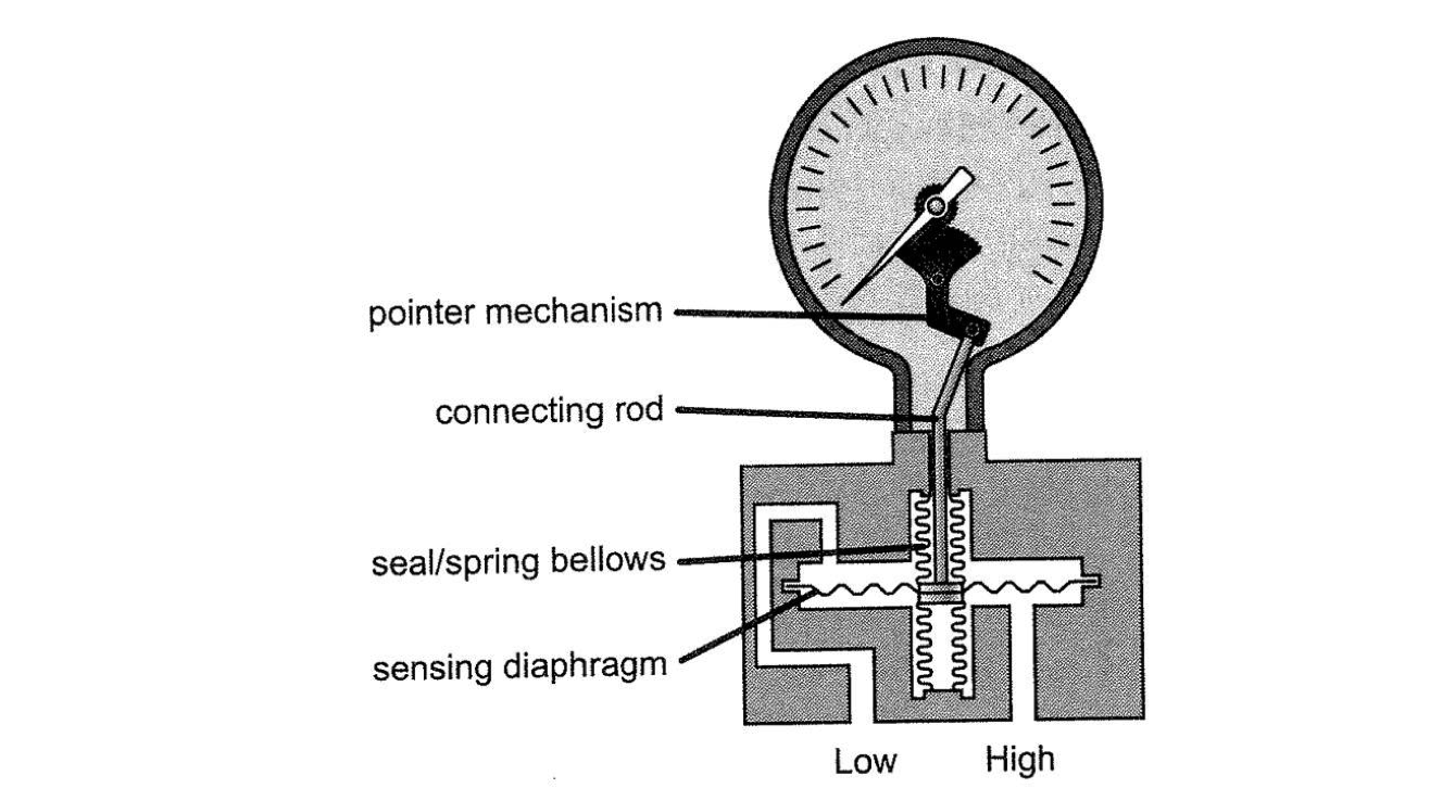
dP Gauge
Principle of Operation:
This example is also a mechanical device, similar to a Bourdon tube
[image 140-2-05]
Strain Gauge Transducer
Principle of Operation:
Group of wires stretch when they are exposed to pressure. Current flows through the wires, and resistance changes as the wires are stressed. Emits an electrical signal.

[image 140-2-06]
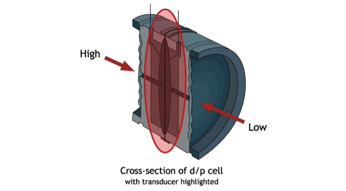
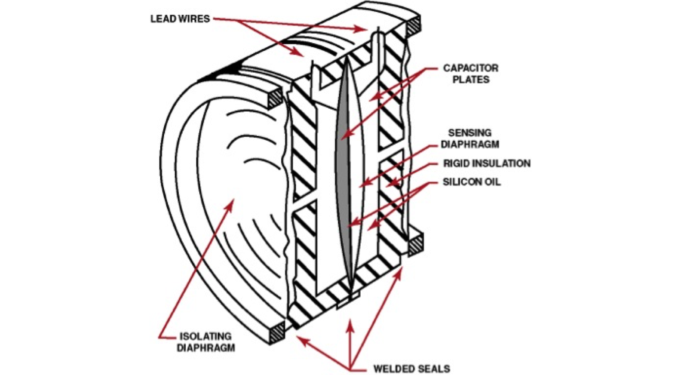
Capacitance Transducer
Principle of Operation:
Two metal capacitor plates are pushed closer together as they are exposed to pressure; distance between the plates changes the amount of electrical charge that the two plates can hold (electrical capacitance). Emits an electrical signal.
[image 140-2-07]
[image 140-2-08]
Pressure transmitters — How to identify them in the field?
- Read the nameplate tag on the instrument
- Should show calibration range
- Will give model number — can look it up
- May include facility tag number
- Look at how the instrument connects to the process
- Sensors have an isolation valve at the process connection
- If a dP cell, then there will be two sensing leads (one may be to atmosphere) — look for H/L stencil on the instrument body (High/Low)
- If a P cell, then there will be one sensing lead
- Be aware that many pressure transmitters are used as level or flow instruments
Differential Pressure
- dP, DP
- P2 — P1
- Difference in pressure between 2 distinct points.
- dP can be used to calculate other process variables, specifically FLOW or LEVEL (we’ll learn more later)
- dP around equipment used for monitoring the fouling or plugging of the equipment (filters).
Absolute Pressure — Pressure scale where 0 = full vacuum
- Pounds/square inch ABSOLUTE
- Total Vacuum is 0 psia
- Normal atmospheric P (sea level) = 14.7 psia
- Most gauges read pressure above atmospheric pressure, called GAUGE pressure — psig
- Normal atmospheric P (sea level) = 0 psig
- Atmospheric pressure changes depending on elevation, conditions, but:
- For practical purposes, psia = psig + 14.7
Pressure Units — many many
- Need for different scales
- Water, mercury, etc. can measure smaller variations in pressure more clearly
- How is ‘in. H2O’ a pressure unit? Isn’t pressure force/area?
- Look at columns of water, pressure
Pressure Units — In. W.C.
- The unit “in. w.c.’ or “in. H2O’ means:
- The pressure is equivalent to the pressure exerted by a column of water that high.
- If you had a column of water that was 1 square inch in cross-sectional area, 27.7 inches high, the weight of that water would be 1 pound. 1 pound/sq. inch = 1 psi
- The pressure exerted by a column of liquid is independent of the diameter of the column.
- WHY is that?
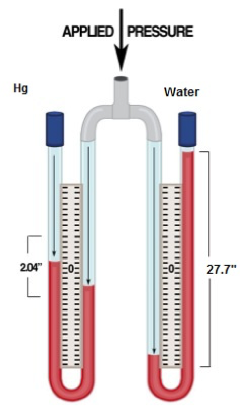
Units — Mercury vs. Water — 1 psi
[image 140-2-09]
Conversions — Unit Equivalency
- psia = psig + 14.7
- psig = psia — 14.7
- 1 psi = 2.04 in. Hg = 27.7 in. H2O = 0.069 bar
- It goes on and on — how to convert between units?
- Learn or look up conversion factors for every change — see Table 2.3….
- Or learn the main ‘equivalencies’ and how to convert that way
Table 2-3, Pressure Unit Conversion Chart
| psi | bar | mbar | In. Hg | In. H2O | mmHg | mmH2O | |
|---|---|---|---|---|---|---|---|
| psi | 1 | 14.504 | 0.014504 | 0.49118 | 0.036127 | 0.019337 | 0.0014223 |
| bar | 0.068946 | 1 | 0.001 | 0.033865 | 0.0024908 | 0.0013332 | 9.8068 x 10⁻⁵ |
| mbar | 68.946 | 1000 | 1 | 33.865 | 2.4908 | 1.3332 | 0.098068 |
| In. Hg | 2.0359 | 29.529 | 0.029529 | 1 | 0.073552 | 0.039368 | 0.0028959 |
| In. H2O | 27.68 | 401.47 | 0.40147 | 13.596 | 1 | 0.53525 | 0.039372 |
| mmHg | 51.714 | 750.06 | 0.75006 | 25.401 | 1.8683 | 1 | 0.073558 |
| mmH2O | 703.05 | 0.10197 | 10.197 | 345.32 | 25.339 | 13.595 | 1 |
| atm | 0.068045 | 0.98692 | 0.00098692 | 0.033422 | 0.0024583 | 0.0013158 | 9.6788 x 10⁻⁵ |
In this type of table, always best to confirm that you’re reading it right.
I know that 27.7 in. H2O = 1 psi, so I can figure out how to read this particular table:
1 of (Column Heading) = (table value) of (Row Heading)
Example: 1 mmHg = 0.53525 in. H2O
Conversion Table 2-3
You can use each column in the table as a string of ‘equivalent units’
Note: Not every table is the same — verify before you calculate. You know that 1 psi = 27.7 in H2O
| psi | bar | mbar | In. Hg | In. H2O | mmHg | mmH2O | |
|---|---|---|---|---|---|---|---|
| psi | 1 | 14.504 | 0.014504 | 0.49118 | 0.036127 | 0.019337 | 0.0014223 |
| bar | 0.068946 | 1 | 0.001 | 0.033865 | 0.0024908 | 0.0013332 | 9.8068 x 10⁻⁵ |
| mbar | 68.946 | 1000 | 1 | 33.865 | 2.4908 | 1.3332 | 0.098068 |
| In. Hg | 2.0359 | 29.529 | 0.029529 | 1 | 0.073552 | 0.039368 | 0.0028959 |
| In. H2O | 27.68 | 401.47 | 0.40147 | 13.596 | 1 | 0.53525 | 0.039372 |
| mmHg | 51.714 | 750.06 | 0.75006 | 25.401 | 1.8683 | 1 | 0.073558 |
| mmH2O | 703.05 | 0.10197 | 10.197 | 345.32 | 25.339 | 13.595 | 1 |
| atm | 0.068045 | 0.98692 | 0.00098692 | 0.033422 | 0.0024583 | 0.0013158 | 9.6788 x 10⁻⁵ |
Equivalency Calcs
1 psi = 2.04 in. Hg = 27.7 in. H2O = 0.069 bar
New units = (known units) x (new equivalent units)
(known equivalent units)
Ex: Convert 50 in. water to psi
New psi = (50 in H2O)/(27.7 in H2)) x (1 psi)
New psi = 1.8 psi
PID, PFD, Symbols Information

[image 140-2-11]
P&ID Detail — Pressure Instruments
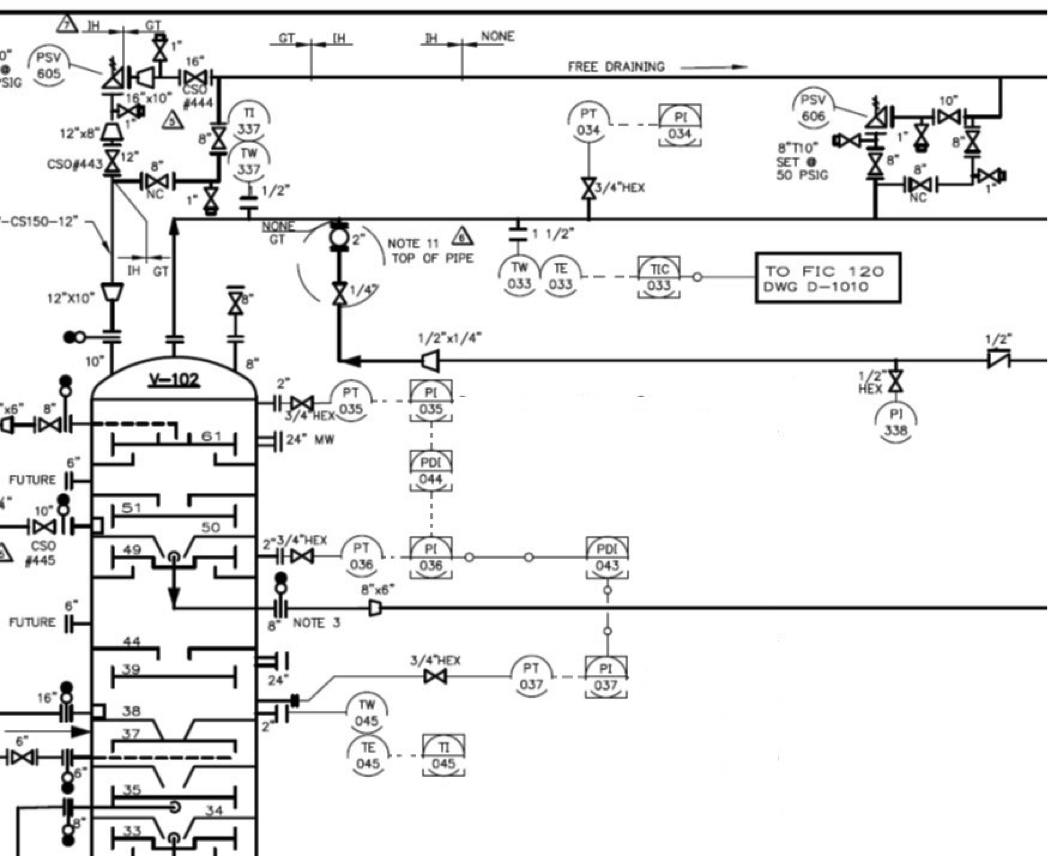
[image 140-2-12]
Reading a P&ID – Instrumentation
- To interpret instrumentation on a P&ID, you apply your own logic to the information given. Some rules of thumb:
- The signal begins at the process and moves outward.
- Signals move in one direction only, through each signal line shown.
- Follow the signal path to describe what the instruments are doing.
- Balloons used for instrumentation provide info on remote/local, mechanical/electrical, etc.